
Page 135 - Semiconductor Manufacturing Handbook
P. 135
Geng(SMH)_CH10.qxd 04/04/2005 19:46 Page 10.8
ION IMPLANTATION AND RAPID THERMAL PROCESSING
10.8 WAFER PROCESSING
10.2.5 Medium-Current Beamlines
The primary objective of medium-current implanters is to deliver a wide range of beam currents, from
a few microamperes to several milliamperes at energies in the range of a few keV to a few hundred
keV. This broad set of expectations for medium-current tools make them among the most versatile for
at least having the capability to perform almost any implant required in typical processing, albeit at
the expense of optimum productivity. There is also a significant variety in the architecture of the
medium-current beamline, but fundamentally, most implementations involve the use of a scanned ion
beam.
The formation of the ion beam again takes place in a manner similar to high-current tools, typi-
cally at energies in the range of 40 to 80 keV. Following the analyzer magnet and resolving aperture,
the beam is typically scanned in the dispersive plane via either an electric or a magnetic scanning
element. 15,16 The scanning takes place at frequencies in the range of 100 to 1000 Hz (slower for mag-
netic scanning where the inductance of the electromagnet poses a limitation) and over an angular
extent of 10 to 20°. Following scanning, the beam must then be made parallel once again before it
is incident on the wafer. This is typically achieved again with either an electrostatic or a magnetic
optical element. Following this parallelizing element, the beam may also be electrostatically deflected
once more to provide energy filtering to remove ions of unwanted energy that may have had coinci-
dental paths through the beamline. Acceleration of the beam to its final energy (which may be as high
as several hundred keV for multiply charged ions) typically occurs following the scanning and par-
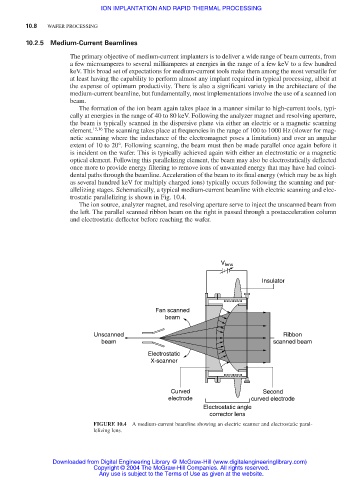
allelizing stages. Schematically, a typical medium-current beamline with electric scanning and elec-
trostatic parallelizing is shown in Fig. 10.4.
The ion source, analyzer magnet, and resolving aperture serve to inject the unscanned beam from
the left. The parallel scanned ribbon beam on the right is passed through a postacceleration column
and electrostatic deflector before reaching the wafer.
V lens
Insulator
Fan scanned
beam
Unscanned Ribbon
beam scanned beam
Electrostatic
X-scanner
Curved Second
electrode curved electrode
Electrostatic angle
corrector lens
FIGURE 10.4 A medium-current beamline showing an electric scanner and electrostatic paral-
lelizing lens.
Downloaded from Digital Engineering Library @ McGraw-Hill (www.digitalengineeringlibrary.com)
Copyright © 2004 The McGraw-Hill Companies. All rights reserved.
Any use is subject to the Terms of Use as given at the website.