
Page 19 - Semiconductor Manufacturing Handbook
P. 19
Geng(SMH)_CH02.qxd 04/04/2005 19:33 Page 2.6
IC DESIGN
2.6 SEMICONDUCTOR FUNDAMENTALS AND BASIC MATERIALS
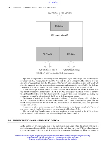
USB Interface to Host Controller
USB slave
AGP bus stimulator IC
AGP master PCI slave
AGP interface to Target PCI interface to Target
FIGURE 2.7 AGP bus stimulator block design example.
Synthesis is the process of converting the RTL design into a gate-level design. Due to the complex-
ity of modern RTL designs, this step must be done with the aid of a computer. The synthesis tool cre-
ates a list of gates and nets from the RTL design. This “netlist” is then input into another tool, which will
place the gates and route the nets according to constraints and optimizations specified by the designer.
This output from the place and route tools becomes the physical layout of the integrated circuit.
A modular design must be created in such a way that any type of model can be interfaced with
any other type of model. For instance, a block in the RTL model phase must still be able to interface
to a different block that is in the behavioral model phase. By doing this, simulation and testing can
occur even when different portions of the IC are in different design phases.
Verification of a design is done by means of a test bench. A test bench is generally coded using
an HDL and should be able to interface to behavioral or RTL code or synthesized gates. The test
bench usually encloses the device under test, and stimulates the behavioral, RTL, and gate-level
designs with vectors.
A successful set of vectors should verify the functionality of the design completely. The set of
test vectors should also be able to detect common gate-level hardware faults.
The test bench should not be coded by the same engineering team that designs the IC. More infor-
mation about IC verification and test bench writing can be found in Ref. 1.
2.6 FUTURE TRENDS AND ISSUES IN IC DESIGN
As IC technology progresses, the size of the transistor is decreasing, while the amount of logic in a
design increases. Because HDLs, logic synthesis tools, and place and route CAD tools have become
more sophisticated, it is now possible to create large, complex digital designs. However, as design
Downloaded from Digital Engineering Library @ McGraw-Hill (www.digitalengineeringlibrary.com)
Copyright © 2004 The McGraw-Hill Companies. All rights reserved.
Any use is subject to the Terms of Use as given at the website.