
Page 210 - Semiconductor Manufacturing Handbook
P. 210
Geng(SMH)_CH14.qxd 04/04/2005 19:52 Page 14.11
CHEMICAL VAPOR DEPOSITION
CHEMICAL VAPOR DEPOSITION 14.11
14.3 COMPONENTS OF A CVD SYSTEM
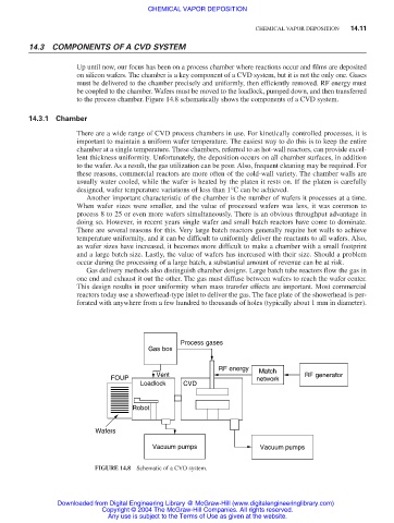
Up until now, our focus has been on a process chamber where reactions occur and films are deposited
on silicon wafers. The chamber is a key component of a CVD system, but it is not the only one. Gases
must be delivered to the chamber precisely and uniformly, then efficiently removed. RF energy must
be coupled to the chamber. Wafers must be moved to the loadlock, pumped down, and then transferred
to the process chamber. Figure 14.8 schematically shows the components of a CVD system.
14.3.1 Chamber
There are a wide range of CVD process chambers in use. For kinetically controlled processes, it is
important to maintain a uniform wafer temperature. The easiest way to do this is to keep the entire
chamber at a single temperature. These chambers, referred to as hot-wall reactors, can provide excel-
lent thickness uniformity. Unfortunately, the deposition occurs on all chamber surfaces, in addition
to the wafer. As a result, the gas utilization can be poor. Also, frequent cleaning may be required. For
these reasons, commercial reactors are more often of the cold-wall variety. The chamber walls are
usually water cooled, while the wafer is heated by the platen it rests on. If the platen is carefully
designed, wafer temperature variations of less than 1°C can be achieved.
Another important characteristic of the chamber is the number of wafers it processes at a time.
When wafer sizes were smaller, and the value of processed wafers was less, it was common to
process 8 to 25 or even more wafers simultaneously. There is an obvious throughput advantage in
doing so. However, in recent years single wafer and small batch reactors have come to dominate.
There are several reasons for this. Very large batch reactors generally require hot walls to achieve
temperature uniformity, and it can be difficult to uniformly deliver the reactants to all wafers. Also,
as wafer sizes have increased, it becomes more difficult to make a chamber with a small footprint
and a large batch size. Lastly, the value of wafers has increased with their size. Should a problem
occur during the processing of a large batch, a substantial amount of revenue can be at risk.
Gas delivery methods also distinguish chamber designs. Large batch tube reactors flow the gas in
one end and exhaust it out the other. The gas must diffuse between wafers to reach the wafer center.
This design results in poor uniformity when mass transfer effects are important. Most commercial
reactors today use a showerhead-type inlet to deliver the gas. The face plate of the showerhead is per-
forated with anywhere from a few hundred to thousands of holes (typically about 1 mm in diameter).
Process gases
Gas box
RF energy Match
Vent RF generator
FOUP network
Loadlock CVD
Robot
Wafers
Vacuum pumps Vacuum pumps
FIGURE 14.8 Schematic of a CVD system.
Downloaded from Digital Engineering Library @ McGraw-Hill (www.digitalengineeringlibrary.com)
Copyright © 2004 The McGraw-Hill Companies. All rights reserved.
Any use is subject to the Terms of Use as given at the website.