
Page 297 - Separation process engineering
P. 297
(8-1)
This looks like a normal top operating line, but there will be differences in the way it is plotted and the
way it is used. The bottom operating line is the normal bottom operating line.
(8-2)
We can plot a McCabe-Thiele diagram by using Figure 8-2B. The top operating line has a slope = L/V, a
, and a y = x intersection of y = x = x . This is shown in Figure 8-3B. Note that
w,dist
x w,dist = x w,α but the top operating line goes through y = x = x w,dist not the equilibrium curve at x w,α . The
top operating line cuts through the equilibrium curve, but the distillation does not operate in this range.
Instead the separation from x w,α to x w,β is done in the liquid-liquid separator. The reflux in Figure 8-3A
and 8-3B has a mole fraction of x w,reflux = x w,β, not the distillate composition as is normally the case. In
the column, x w,reflux and y w,1 are passing steams and are on the operating line in Figure 8-3B. Stepping off
the remaining stages follows the normal procedure.
The vapor of mole fraction y w,1 is condensed and sent to the settler. The mass balances for the settler are
straightforward and are illustrated later in Example 8-1.
What can we do if we want a purer water product?
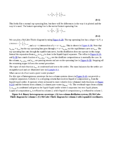
For this type of heterogeneous azeotrope the two-column systems shown in Figure 8-4A can provide a
complete separation. Column 2 is a stripping column that receives liquid of composition x from the
α
liquid-liquid settler. It operates where n-butanol is more volatile (low n-butanol mole fractions on Figure
8-2A) and the bottoms from column 2 is almost pure water (x B,bot ~ 0). The overhead vapor from column
2, y 1,col2 is condensed and goes to the liquid-liquid settler where it separates into two liquid phases.
Liquid of composition x is refluxed to column 2, while liquid of composition x is refluxed to column 1.
β
α
Figure 8-4. Binary heterogeneous azeotrope; (A) two-column distillation system, (B) McCabe-
Thiele diagram for column 1. (C) McCabe-Thiele diagram for column 2 with expanded coordinates.