
Page 122 - Shale Shakers Drilling Fluid Systems
P. 122
SHALE SHAKER DESIGN 105
high vibration speeds, the peak force, in pounds rotary weights are aligned so that the acceleration
(from the peak acceleration), can be calculated is 45° to the screen surface. The higher liquid ca-
from the equation: pacity of linear motion shale shakers for the same
mesh screens on unbalanced elliptical or circular
motion shakers is primarily related to the fact that
a pool of drilling fluid is created at the entry end
of the shale shaker. The linear motion moves the
Therefore, the force available on the screen sur- solids out of the pool, across the screen, and off the
face is a function of the unbalanced weight (w), end of the screen.
the eccentricity (e), and the rotation speed (N). On a linear motion shaker with a 0.13-in. stroke
Stroke length for a given design depends on the at 1500 rpm, the maximum acceleration is at an
amount of eccentric weight and its distance from angle of 45° to the shale shaker deck. The "G"-fac-
the center of rotation. Increasing the weight tor would be 4.15. The acceleration is measured
eccentricity and/or the rpm increases the "G"- in the direction of the stroke. If the shale shaker
factor. The "G"-factor is an indication of only the deck is tilted at an upward angle of 5° from the
acceleration of the vibrating basket and not nec- horizontal deck, the stroke remains the same. The
essarily its performnce. Every shaker design has component of the stroke parallel to the screen
a practical "G"-factor limit. Most shaker baskets transports the solids up the 5° incline.
are vibrated with a five horsepower or smaller
motor and produce 2 to 7 G's of thrust to the vi-
brating basket. Relationship of "C"-factor to Stroke
Conventional shale shakers usually provide and Speed of Rotation
a "G"-factor of less than 3; fine screen shale
shakers usually provide a "G"-factor between 4 An unbalanced rotating weight vibrates the screen
and 6. Some shale shakers can provide as much deck. The amount of unbalanced weight, com-
as 8 G's. The higher the "G"-factor, the greater bined with the speed of rotation, will yield the "G"-
the solids separation possible and, generally, the factor imparted to the screen deck. The stroke is
shorter the screen life. The higher the solids ca- determined by the amount of unbalanced weight
pacity, the less tendency there is for the screens and its distance from the center of rotation and
to blind. the weight of the shale shaker deck. (This assumes
In unbalanced elliptical and circular vibration that the vibrator frequency is much larger than the
motion designs, only a portion of the energy trans- natural frequency of the shaker deck.) The stroke
ports the cuttings in the proper direction. The re- is independent of the rotary speed.
mainder is lost, due to the peculiar shape of the The "G"-factor can be increased by increasing
screen bed orbit, and is manifested as solids becom- the stroke, rpm, or both. It can also be decreased
ing nondirectional or traveling the wrong direction in the same manner. The stroke must be increased
on the screen surface. Linear motion designs pro- by the inverse square of the rpm reduction to hold
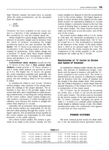
vide positive conveyance of solids throughout the the "G"-factor constant. Examples are given in
vibratory cycle because the motion is straight-line Table 3-1 to hold 5 G's constant while varying the
rather than elliptical or circular. stroke length at different values of rpm. The shaker
Generally, the acceleration forces perpendicular manufacturers select the combination that appears
to the screen surface are responsible for the liq- to work best for their machine.
uid and solids passing through the screen, or the
liquid capacity. The acceleration forces parallel to
the screen surface are responsible for the solids POWER SYSTEMS
transport, or the solids capacity.
On a linear motion shaker, the motion is gen- The most common power source for shale shak-
erally at an angle to the screen. Usually, the two ers is the rig electrical power generator system.
TABLE 3-1
5 G's @ 0.44" stroke at 900 rpm 4 G's @ 0.35" stroke at 900 rpm
5 G's @ 0.24" stroke at 1200 rpm 4 G's @ 0.20" stroke at 1200 rpm
5 G's @ 0.16" stroke at 1500 rpm 4 G's @ 0.13" stroke at 1500 rpm
5 G's @ 0.11" stroke at 1800 rpm 4 G's @ 0.09" stroke at 1800 rpm