
Page 118 - Shale Shakers Drilling Fluid Systems
P. 118
SHALE SHAKER DESIGN 101
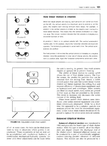
How linear motion is created:
When two equal weights are rotating, each about its own center as shown
on the left, the vertical velocity is a maximum value in position A. At this
point, the weights start moving vertically more slowly. For example, in
position B the vertical velocity is smaller as the weights start moving in a
more lateral direction. This means that the vertical acceleration is a nega-
tive value. The circular rotation indicates that the velocity is changing as a
sinusoidal function of time.
At position C there is no vertical velocity left. The vertical acceleration
reaches zero. At this position, clearly the horizontal velocities are equal and
opposite. The horizontal accelerations cancel each other. The vertical accel-
erations are additive.
The final position D shows that the vertical velocity is increasing in a negative
direction. Since the acceleration is time rate of change velocity, the accelera-
tion is a positive value. Again the horizontal components cancel each other.
the unit is running. In general, fine mesh screens
require an upward tilt to prevent flooding.
The ability of linear motion to convey uphill
allows the use of finer shaker screens. The finer
the screen, the smaller the particles that can be
removed from the drilling fluid. Hence, a solids
control system that uses fine screen linear motion
shakers will better maintain the drilling fluid and
improve efficiency of downstream equipment such
as hydrocyclones and centrifuges. When screens
are tilted too much uphill, many solids are ground
to finer sizes as they are pounded by the screen.
This tends to increase—not decrease—the solids
content of the drilling fluid.
When linear motion shale shakers were intro-
duced, other solids removal equipment was some-
times erroneously eliminated. While for a short
time this appeared to be a solution, particle size
analyses proved the need for downstream equip-
ment. Linear motion shale shakers should not be ex-
pected to replace the entire solids removal system).
Balanced Elliptical Motion
FIGURE 3-9. Adjustable angle drive system.
Balanced elliptical motion was introduced in
1992 and provides the fourth type of shale shaker
of +6°. In some cases, the beds can be tilted down- motion. With this type of motion, all of the ellipse
ward to help in situations where gumbo is en- axes are sloped toward the discharge end of
countered. These movements of bed on skid can the shaker screen. Balanced elliptical motion can
be accomplished with mechanical, hydraulic, or be produced by a pair of eccentrically weighted,
combination mechanical/hydraulic systems. On counter-rotating parallel vibrators of different
some units these adjustments can be made while masses. This motion can also be produced by a