
Page 116 - Shale Shakers Drilling Fluid Systems
P. 116
SHALE SHAKER DESIGN 99
units allowed the first practical use of 80- to 100-
mesh screens.
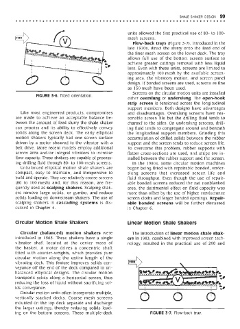
Flow-back trays (Figure 3-7), introduced in the
late 1970s, direct the slurry onto the feed end of
the finer mesh screen on the lower deck. The tray
allows full use of the bottom screen surface to
achieve greater cuttings removal with less liquid
loss. Even with these units, screens are limited to
approximately 100 mesh by the available screen-
ing area, the vibratory motion, and screen panel
design. If bonded screens are used, screens as fine
as 150 mesh have been used.
Screens on the circular motion units are installed
FIGURE 3-6. Tilted orientation.
either overslung or underslung. The open-hook
strip screen is tensioned across the longitudinal
support members. Both designs have advantages
Like most engineered products, compromises and disadvantages. Overslung screens have rea-
are made to achieve an acceptable balance be- sonable screen life but the drilling fluid tends to
tween the amount of feed slurry the shale shaker channel to the sides. On underslung screens, drill-
can process and its ability to effectively convey ing fluid tends to congregate around and beneath
solids along the screen deck. The early elliptical the longitudinal support members. Grinding this
motion shakers typically had one screen surface accumulation of drilled solids between the rubber
driven by a motor sheaved to the vibrator with a support and the screen tends to reduce screen life.
belt drive. More recent models employ additional To overcome this problem, rubber supports with
screen area and/or integral vibrators to increase flatter cross-sections are used, and strips are in-
flow capacity. These shakers are capable of process- stalled between the rubber support and the screen.
ing drilling fluid through 80- to 100-mesh screens. In the 1980s, some circular motion machines
Unbalanced elliptical motion shale shakers are began being fitted with repairable bonded, under-
compact, easy to maintain, and inexpensive to slung screens that increased screen life and
build and operate. They use relatively coarse screens fluid throughput. Even though the use of repair-
(80 to 100 mesh) and, for this reason, are fre- able bonded screens reduced the net nonblanked
quently used as scalping shakers. Scalping shak- area, the detrimental effect on fluid capacity was
ers remove large solids, or gumbo, and reduce more than offset by the use of higher conductance
solids loading on downstream shakers. The use of screen cloths and larger bonded openings. Repair-
scalping shakers in cascading systems is dis- able bonded screens will be further discussed
cussed in Chapter 4. in Chapter 6.
Circular Motion Shale Shakers Linear Motion Shale Shakers
Circular (balanced) motion shakers were The introduction of linear motion shale shak-
introduced in 1963. These shakers have a single ers in 1983, combined with improved screen tech-
vibrator shaft located at the center mass of nology, resulted in the practical use of 200 and
the basket. A motor drives a concentric shaft
fitted with counter-weights, which provides pure
circular motion along the entire length of the
vibrating deck. This feature improves solids con-
veyance off the end of the deck compared to un-
balanced elliptical designs. The circular motion
transports solids along a horizontal screen, thus
reducing the loss of liquid without sacrificing sol-
ids conveyance.
Circular motion units often incorporate multiple,
vertically stacked decks. Coarse mesh screens
mounted on the top deck separate and discharge
the larger cuttings, thereby reducing solids load-
ing on the bottom screens. These multiple-deck FIGURE 3-7. Flow-back tray.