
Page 119 - Shale Shakers Drilling Fluid Systems
P. 119
102 SHALE SHAKERS AND DRILLING FLUID SYSTEMS
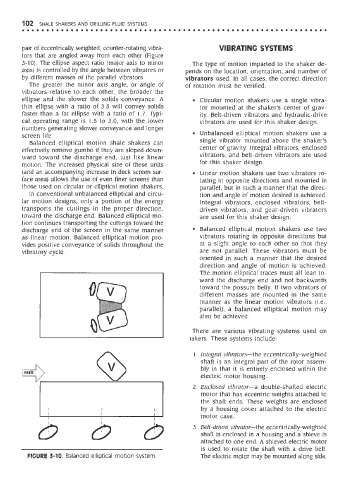
pair of eccentrically weighted, counter-rotating vibra- VIBRATING SYSTEMS
tors that are angled away from each other (Figure
3-10). The ellipse aspect ratio (major axis to minor The type of motion imparted to the shaker de-
axis) is controlled by the angle between vibrators or pends on the location, orientation, and number of
by different masses of the parallel vibrators. vibrators used. In all cases, the correct direction
The greater the minor axis angle, or angle of of rotation must be verified.
vibrators relative to each other, the broader the
ellipse and the slower the solids conveyance. A • Circular motion shakers use a single vibra-
thin ellipse with a ratio of 3.5 will convey solids tor mounted at the shaker's center of grav-
faster than a fat ellipse with a ratio of 1.7. Typi- ity. Belt-driven vibrators and hydraulic-drive
cal operating range is 1.5 to 3.0, with the lower vibrators are used for this shaker design.
numbers generating slower conveyance and longer
screen life. • Unbalanced elliptical motion shakers use a
Balanced elliptical motion shale shakers can single vibrator mounted above the shaker's
effectively remove gumbo if they are sloped down- center of gravity. Integral vibrators, enclosed
ward toward the discharge end, just like linear vibrators, and belt-driven vibrators are used
motion. The increased physical size of these units for this shaker design.
(and an accompanying increase in deck screen sur- • Linear motion shakers use two vibrators ro-
face area) allows the use of even finer screens than tating in opposite directions and mounted in
those used on circular or elliptical motion shakers. parallel, but in such a manner that the direc-
In conventional unbalanced elliptical and circu- tion and angle of motion desired is achieved.
lar motion designs, only a portion of the energy Integral vibrators, enclosed vibrators, belt-
transports the cuttings in the proper direction, driven vibrators, and gear-driven vibrators
toward the discharge end. Balanced elliptical mo- are used for this shaker design.
tion continues transporting the cuttings toward the
discharge end of the screen in the same manner • Balanced elliptical motion shakers use two
as linear motion. Balanced elliptical motion pro- vibrators rotating in opposite directions but
vides positive conveyance of solids throughout the at a slight angle to each other so that they
vibratory cycle. are not parallel. These vibrators must be
oriented in such a manner that the desired
direction and angle of motion is achieved.
The motion elliptical traces must all lean to-
ward the discharge end and not backwards
toward the possum belly. If two vibrators of
different masses are mounted in the same
manner as the linear motion vibrators (i.e.,
parallel), a balanced elliptical motion may
also be achieved.
There are various vibrating systems used on
lakers. These systems include:
1. Integral vibrators—the eccentrically-weighted
shaft is an integral part of the rotor assem-
bly in that it is entirely enclosed within the
electric motor housing.
2. Enclosed vibrator—a double-shafted electric
motor that has eccentric weights attached to
the shaft ends. These weights are enclosed
by a housing cover attached to the electric
motor case.
3. Belt-driven vibrator—the eccentrically-weighted
shaft is enclosed in a housing and a shieve is
attached to one end. A shieved electric motor
is used to rotate the shaft with a drive belt.
FIGURE 3-10. Balanced elliptical motion system. The electric motor may be mounted along side,