
Page 120 - Shale Shakers Drilling Fluid Systems
P. 120
SHALE SHAKER DESIGN 103
above, or behind the shaker depending on the screens were attached to the bed of the shaker by
model. It may also be mounted on the shaker pulling the screen down onto the bed from the
bed along with the vibrator assembly. top. This resulted in a screening area completely
free of obstacles. Modern shale shaker bed design
4. Dual-shafted, belt-driven vibrator—this system
has also increased the number of support ribs
is similar to the above description except located beneath the screen to aid in fine mesh
that it has two vibrator shafts rotating in op- support and to reduce the amount of "crown," or
posite directions and driven by one electric "bow," necessary to properly tension screen pan-
motor with a drive belt.
els. Occasionally, fluid traveled from the high, cen-
5. Gear drive—a double-shafted, electric motor ter of the screen and flowed down the sides.
drives a sealed gear box, which in turn rotates Most circular motion shale shakers were built
two vibrator shafts in opposite directions. with a double deck, which means fluid flowed over
and through the top screen onto a finer mesh
6. Hydraulic drive—a hydraulic drive motor is screen immediately below. This design led to some
attached directly to a vibrator shaft, which is
operational problems because the bottom screen
enclosed in a housing. The hydraulic motor
was not easily visible. Generally, a flashlight was
must have a hydraulic power unit that needed to inspect the lower screen, and a torn
includes an electric motor and a hydraulic
screen could remain in operation for a long
pump. The hydraulic-drive motor powers the
time before it was noticed and changed. This cre-
vibrator shaft.
ated problems with solids removal because the
bottom screen did not provide the intended finer
screening. Some manufacturers installed backflow
DECK DESIGN
pans beneath the top screen to direct the flow
through the entire surface area of the lower screen,
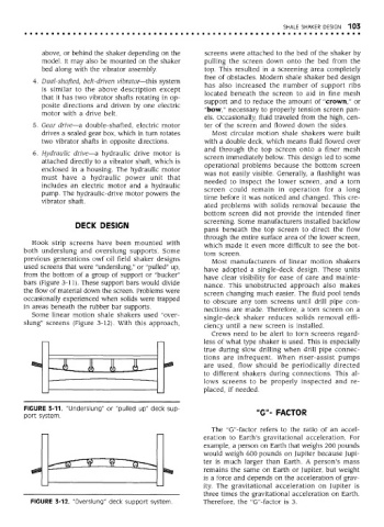
Hook strip screens have been mounted with
which made it even more difficult to see the bot-
both underslung and overslung supports. Some
tom screen.
previous generations owf oil field shaker designs
Most manufacturers of linear motion shakers
used screens that were "underslung/' or "pulled" up, have adopted a single-deck design. These units
from the bottom of a group of support or "bucker" have clear visibility for ease of care and mainte-
bars (Figure 3-11). These support bars would divide nance. This unobstructed approach also makes
the flow of material down the screen. Problems were screen changing much easier. The fluid pool tends
occasionally experienced when solids were trapped
to obscure any torn screens until drill pipe con-
in areas beneath the rubber bar supports.
nections are made. Therefore, a torn screen on a
Some linear motion shale shakers used "over-
single-deck shaker reduces solids removal effi-
slung" screens (Figure 3-12). With this approach, ciency until a new screen is installed.
Crews need to be alert to torn screens regard-
less of what type shaker is used. This is especially
true during slow drilling when drill pipe connec-
tions are infrequent. When riser-assist pumps
are used, flow should be periodically directed
to different shakers during connections. This al-
lows screens to be properly inspected and re-
placed, if needed.
FIGURE 3-11. "Underslung" or "pulled up" deck sup-
port system. "G"- FACTOR
The "G"-factor refers to the ratio of an accel-
eration to Earth's gravitational acceleration. For
example, a person on Earth that weighs 200 pounds
would weigh 600 pounds on Jupiter because Jupi-
ter is much larger than Earth. A person's mass
remains the same on Earth or Jupiter, but weight
is a force and depends on the acceleration of grav-
ity. The gravitational acceleration on Jupiter is
three times the gravitational acceleration on Earth.
FIGURE 3-12. "Overslung" deck support system. Therefore, the "G"-factor is 3.