
Page 147 - Shale Shakers Drilling Fluid Systems
P. 147
130 SHALE SHAKERS AND DRILLING FLUID SYSTEMS
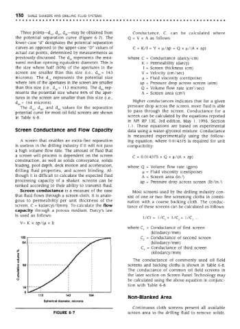
Three points—d l6, d so, d 84—may be obtained from Conductance, C, can be calculated where
the potential separation curve (Figure 6-7). The Q = V x A as follows:
lower-case "d" designates the potential separation
curves as opposed to the upper-case "D" values of C = K/l = V x ji/Ap = Q x n/(A x Ap)
actual cut points, determined by measurements as
previously discussed. The d 50 represents the mea- where C = Conductance (darcy/cm)
sured median opening equivalent diameter. This is K = Permeability (darcy)
the size where half (50%) of the apertures in the 1 = Screen thickness (cm)
screen are smaller than this size (i.e., d 50 = 143 V = Velocity (cm/sec)
microns). The d 16 represents the potential size |i = Fluid viscosity (centipoise)
where 16% of the apertures in the screen are smaller Ap = Pressure drop across screen (atm)
than this size (i.e., d, 6 = 113 microns). The d 84 rep- Q = Volume flow rate (cmVsec)
2
resents the potential size where 84% of the aper- A = Screen area (cm )
tures in the screen are smaller than this size (i.e.,
d 84 = 154 microns). Higher conductances indicates that for a given
The d 16, d 50, and d 84 values for the separation pressure drop across the screen, more fluid is able
potential curve for most oil field screens are shown to pass through the screen. Conductance for a
in Table 6-8. screen can be calculated by the equations reported
in API RP 13E, 3rd edition, May 1, 1995, Section
1.1. These equations are based on experimental
Screen Conductance and Flow Capacity data using a water-glycerol mixture. Conductance
is measured experimentally using the follow-
A screen that enables an extra-fine separation ing equation, where 0.014375 is required for unit
is useless in the drilling industry if it will not pass compatibility:
a high volume flow rate. The amount of fluid that
a screen will process is dependent on the screen C = 0.014375 x Q x |j/(A x Ap)
construction, as well as solids conveyance, solids
loading, pool depth, deck motion and acceleration, where Q = Volume flow rate (gpm)
drilling fluid properties, and screen blinding. Al- )j, = Fluid viscosity (centipoise)
though it is difficult to calculate the expected fluid A = Screen area (in. )
2
processing capacity of a shaker, screens can be Ap = Pressure drop across screen (lb/in. )
2
ranked according to their ability to transmit fluid.
Screen conductance is a measure of the ease Most screens used by the drilling industry con-
that fluid flows through a screen cloth. It is analo- sist of one or two fine screening cloths in combi-
gous to permeability per unit thickness of the nation with a coarse backing cloth. The conduc-
screen, C = k(darcy)/l(mm). To calculate the flow tance of these screens can be calculated as follows:
capacity through a porous medium, Darcy's law
is used as follows:
1/Ct = 1/C,+ 1/C 2 + 1/C 3 ...
where C, = Conductance of first screen
(kilodarcy/mm)
C 2 = Conductance of second screen
(kilodarcy/mm)
C 3 = Conductance of third screen
(kilodarcy/mm)
The conductance of commonly used oil field
screens and backing cloths is shown in Table 6-8.
The conductance of common oil field screens in
the later section on Screen Panel Technology may
be calculated using the above equation in conjunc-
tion with Table 6-8.
Non-Blanked Area
Continuous cloth screens present all available
FIGURE 6-7 screen area to the drilling fluid to remove solids.