Page 340 - Shigley's Mechanical Engineering Design
P. 340

bud29281_ch06_265-357.qxd  11/30/2009  4:23 pm  Page 315 pinnacle s-171:Desktop Folder:Temp Work:Don't Delete (Jobs):MHDQ196/Budynas:


                                                                               Fatigue Failure Resulting from Variable Loading  315
                                               • First-quadrant fatigue failure locus is concave-upward (Smith-Dolan), for example,
                                                 and as flat as Goodman. Brittle materials are more sensitive to midrange stress, being
                                                 lowered, but compressive midrange stresses are beneficial.
                                               • Not enough work has been done on brittle fatigue to discover insightful generalities,
                                                 so we stay in the first and a bit of the second quadrant.
                                               The most likely domain of designer use is in the range from −S ut ≤ σ m ≤ S ut . The
                                               locus in the first quadrant is Goodman, Smith-Dolan, or something in between. The por-
                                               tion of the second quadrant that is used is represented by a straight line between the
                                               points −S ut , S ut and 0, S e , which has the equation

                                                                   S e
                                                         S a = S e +  − 1 S m    −S ut ≤ S m ≤ 0 (for cast iron)  (6–53)
                                                                   S ut
                                               Table A–24 gives properties of gray cast iron.  The endurance limit stated is really
                                               k a k b S and only corrections k c , k d , k e , and k f need be made. The average k c for axial

                                                   e
                                               and torsional loading is 0.9.


                                                                                                      3
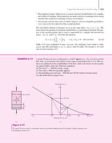
                            EXAMPLE 6–13       A grade 30 gray cast iron is subjected to a load F applied to a 1 by  -in cross-section
                                                                                                      8
                                                        1
                                               link with a  -in-diameter hole drilled in the center as depicted in Fig. 6–31a. The sur-
                                                        4
                                               faces are machined. In the neighborhood of the hole, what is the factor of safety guard-
                                               ing against failure under the following conditions:
                                               (a) The load F = 1000 lbf tensile, steady.
                                               (b) The load is 1000 lbf repeatedly applied.
                                               (c) The load fluctuates between −1000 lbf and 300 lbf without column action.
                                               Use the Smith-Dolan fatigue locus.


                                                                  Alternating stress,   a
                          F
                                                                      S ut


                         1 in     1  in D. drill          r = –1.86
                                  4
                                                                         S  = 18.5 kpsi
                                                                         a

                                                                         S e
                                                                                 r = 1
                                  3  in
                                  8
                                                                           = 7.63
                                                                        S a
                                                               S
                          F                                     m
                                          –S ut              –9.95      0     7.63 10     20       30 S ut
                                                                 Midrange stress   , kpsi
                                                                           m
                         (a)                                           (b)
                       Figure 6–31
                       The grade 30 cast-iron part in axial fatigue with (a) its geometry displayed and (b) its designer’s fatigue diagram for the
                       circumstances of Ex. 6–13.
   335   336   337   338   339   340   341   342   343   344   345