
Page 361 - Shigley's Mechanical Engineering Design
P. 361
bud29281_ch06_265-357.qxd 12/02/2009 9:46 pm Page 336 pinnacle s-171:Desktop Folder:Temp Work:Don't Delete (Jobs):MHDQ196/Budynas:
336 Mechanical Engineering Design
From Eq. (6–78),
K t 1.65
K f = √ = = 1.51
2(K t − 1) a 2(1.65 − 1) 0.2014
1 + √ 1 + √
K t r 1.65 3
which is 2.5 percent lower than what was found in Ex. 6–6.
From Table 6–15, C Kf = 0.11. Thus from Eq. (6–79),
Answer K f = 1.51 LN(1, 0.11)
From Eq. (6–77), with K t = 1.65
1.51 − 1
¯ q = = 0.785
1.65 − 1
¯
C K f K f 0.11(1.51)
C q = = = 0.326
K f − 1 1.51 − 1
¯
ˆ σ q = C q ¯q = 0.326(0.785) = 0.256
So,
Answer q = LN(0.785, 0.256)
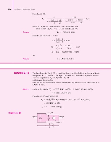
EXAMPLE 6–19 The bar shown in Fig. 6–37 is machined from a cold-rolled flat having an ultimate
strength of S ut = LN(87.6, 5.74) kpsi. The axial load shown is completely reversed.
The load amplitude is F a = LN(1000, 120) lbf.
(a) Estimate the reliability.
(b) Reestimate the reliability when a rotating bending endurance test shows that S =
e
LN(40, 2) kpsi.
Solution (a) From Eq. (6–70), S = 0.506S ut LN(1, 0.138) = 0.506(87.6)LN(1, 0.138)
¯
e
= 44.3LN(1, 0.138) kpsi
From Eq. (6–72) and Table 6–10,
k a = 2.67S ¯ −0.265 LN(1, 0.058) = 2.67(87.6) −0.265 LN(1, 0.058)
ut
= 0.816LN(1, 0.058)
k b = 1 (axial loading)
Figure 6–37 16 3 -in R.
1000 lbf 1000 lbf
1
1
2in 1in
4 2
3
1 in 4 -in D.
4