Page 465 - Shigley's Mechanical Engineering Design
P. 465
bud29281_ch08_409-474.qxd  12/16/2009  7:11 pm  Page 440 pinnacle 203:MHDQ196:bud29281:0073529281:bud29281_pagefiles:


                 440    Mechanical Engineering Design
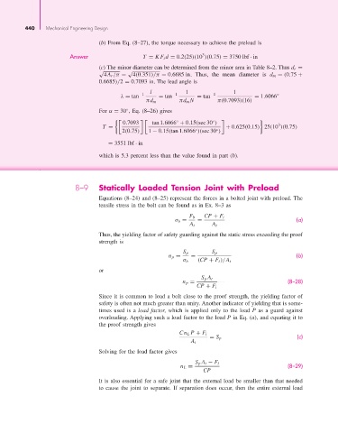
                                          (b) From Eq. (8–27), the torque necessary to achieve the preload is

                                                                             3
                                Answer                   T = KF i d = 0.2(25)(10 )(0.75) = 3750 lbf · in
                                          (c) The minor diameter can be determined from the minor area in Table 8–2. Thus d r =
                                          √         √
                                            4A r /π =  4(0.351)/π = 0.6685 in.  Thus, the mean diameter is  d m = (0.75 +
                                          0.6685)/2 = 0.7093 in. The lead angle is
                                                           l            1               1
                                                 λ = tan −1   = tan −1      = tan −1           = 1.6066 ◦
                                                          πd m       πd m N        π(0.7093)(16)
                                          For α = 30 , Eq. (8–26) gives
                                                   ◦
                                                  0.7093    tan 1.6066 + 0.15(sec 30 )
                                                                                 ◦

                                                                    ◦
                                                                                                       3
                                           T =                                       + 0.625(0.15) 25(10 )(0.75)
                                                  2(0.75)  1 − 0.15(tan 1.6066 )(sec 30 )
                                                                           ◦
                                                                                  ◦
                                             = 3551 lbf · in
                                          which is 5.3 percent less than the value found in part (b).


                                  8–9     Statically Loaded Tension Joint with Preload
                                          Equations (8–24) and (8–25) represent the forces in a bolted joint with preload. The
                                          tensile stress in the bolt can be found as in Ex. 8–3 as

                                                                         F b  CP + F i
                                                                    σ b =   =                                 (a)
                                                                         A t     A t
                                          Thus, the yielding factor of safety guarding against the static stress exceeding the proof
                                          strength is
                                                                       S p       S p
                                                                  n p =  =                                    (b)
                                                                       σ b  (CP + F i )/A t
                                          or
                                                                             S p A t
                                                                       n p =                               (8–28)
                                                                           CP + F i
                                          Since it is common to load a bolt close to the proof strength, the yielding factor of
                                          safety is often not much greater than unity. Another indicator of yielding that is some-
                                          times used is a  load factor, which is applied only to the load  P as a guard against
                                          overloading. Applying such a load factor to the load P in Eq. (a), and equating it to
                                          the proof strength gives

                                                                      Cn L P + F i
                                                                                = S p                         (c)
                                                                         A t
                                          Solving for the load factor gives

                                                                           S p A t − F i
                                                                      n L =                                (8–29)
                                                                              CP
                                          It is also essential for a safe joint that the external load be smaller than that needed
                                          to cause the joint to separate. If separation does occur, then the entire external load

