Page 470 - Shigley's Mechanical Engineering Design
P. 470

bud29281_ch08_409-474.qxd  12/16/2009  7:11 pm  Page 445 pinnacle 203:MHDQ196:bud29281:0073529281:bud29281_pagefiles:


                                                                       Screws, Fasteners, and the Design of Nonpermanent Joints  445
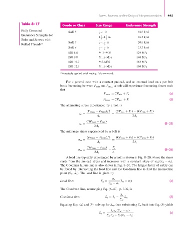
                       Table 8–17               Grade or Class       Size Range        Endurance Strength

                       Fully Corrected              SAE 5              1 –1 in                 18.6 kpsi
                                                                       4
                       Endurance Strengths for                         1 –1 1  in              16.3 kpsi
                                                                        1
                       Bolts and Screws with                           1 8  1 2
                       Rolled Threads*              SAE 7              4  –1 2  in             20.6 kpsi
                                                    SAE 8              1 –1  1  in             23.2 kpsi
                                                                       4  2
                                                    ISO 8.8            M16–M36                129 MPa
                                                    ISO 9.8            M1.6–M16               140 MPa
                                                    ISO 10.9           M5–M36                 162 MPa
                                                    ISO 12.9           M1.6–M36               190 MPa

                                               *Repeatedly applied, axial loading, fully corrected.

                                                  For a general case with a constant preload, and an external load on a per bolt
                                               basis fluctuating between P min and P max, a bolt will experience fluctuating forces such
                                               that
                                                                                                                  (a)
                                                                          F bmin = CP min + F i
                                                                                                                  (b)
                                                                         F bmax = CP max + F i
                                               The alternating stress experienced by a bolt is
                                                               (F bmax − F bmin )/2  (CP max + F i ) − (CP min + F i )
                                                          σ a =                =
                                                                     A t                   2A t
                                                               C(P max − P min )
                                                          σ a =                                                (8–35)
                                                                    2A t
                                               The midrange stress experienced by a bolt is
                                                               (F bmax + F bmin )/2  (CP max + F i ) + (CP min + F i )
                                                          σ m =                =
                                                                      A t                  2A t
                                                               C(P max + P min )  F i
                                                          σ m =              +                                 (8–36)
                                                                    2A t       A t
                                                  A load line typically experienced by a bolt is shown in Fig. 8–20, where the stress
                                               starts from the preload stress and increases with a constant slope of  σ a /(σ m − σ i ).
                                               The Goodman failure line is also shown in Fig. 8–20. The fatigue factor of safety can
                                               be found by intersecting the load line and the Goodman line to find the intersection
                                               point (S m, S a). The load line is given by
                                                                               σ a
                                               Load line:               S a =      (S m − σ i )                   (a)
                                                                             σ m − σ i
                                               The Goodman line, rearranging Eq. (6–40), p. 306, is
                                                                                    S e
                                               Goodman line:               S a = S e −  S m                       (b)
                                                                                    S ut
                                               Equating Eqs. (a) and (b), solving for S m , then substituting S m back into Eq. (b) yields
                                                                              S e σ a (S ut − σ i )
                                                                       S a =                                      (c)
                                                                            S ut σ a + S e (σ m − σ i )
   465   466   467   468   469   470   471   472   473   474   475