Page 467 - Shigley's Mechanical Engineering Design
P. 467

bud29281_ch08_409-474.qxd  12/16/2009  7:11 pm  Page 442 pinnacle 203:MHDQ196:bud29281:0073529281:bud29281_pagefiles:


                 442    Mechanical Engineering Design
                                                                              8
                                                                      7
                                          (85 kpsi up to a diameter of 1 in). Bowman recommends a preload of 75 percent of
                                          proof load, which is about the same as the RB&W recommendations for reused bolts.
                                          In view of these guidelines, it is recommended for both static and fatigue loading that
                                          the following be used for preload:
                                                                 for nonpermanent connections, reused fasteners
                                                       0.75F p
                                                 F i =                                                     (8–31)
                                                       0.90F p   for permanent connections
                                          where  F p is the proof load, obtained from the equation

                                                                        F p = A t S p                      (8–32)
                                          Here S p is the proof strength obtained from Tables 8–9 to 8–11. For other materials,
                                          an approximate value is S p = 0.85S y . Be very careful not to use a soft material in a
                                          threaded fastener. For high-strength steel bolts used as structural steel connectors, if
                                          advanced tightening methods are used, tighten to yield.
                                              You can see that the RB&W recommendations on preload are in line with what
                                          we have encountered in this chapter. The purposes of development were to give the
                                          reader the perspective to appreciate Eqs. (8–31) and a methodology with which to
                                          handle cases more specifically than the recommendations.


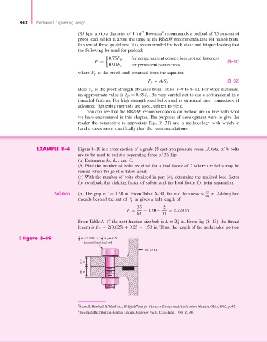
                        EXAMPLE 8–4       Figure 8–19 is a cross section of a grade 25 cast-iron pressure vessel. A total of N bolts
                                          are to be used to resist a separating force of 36 kip.
                                          (a) Determine k b , k m , and C.
                                          (b) Find the number of bolts required for a load factor of 2 where the bolts may be
                                          reused when the joint is taken apart.
                                          (c) With the number of bolts obtained in part (b), determine the realized load factor
                                          for overload, the yielding factor of safety, and the load factor for joint separation.

                                Solution  (a) The grip is l = 1.50 in. From Table A–31, the nut thickness is   35  in. Adding two
                                                                                                 64
                                                                2
                                          threads beyond the nut of   11  in gives a bolt length of
                                                                   35          2
                                                               L =    + 1.50 +   = 2.229 in
                                                                   64         11
                                                                                     1
                                          From Table A–17 the next fraction size bolt is L = 2 in. From Eq. (8–13), the thread
                                                                                     4
                                          length is L T = 2(0.625) + 0.25 = 1.50 in. Thus, the length of the unthreaded portion
                  Figure 8–19             5 8  in-11 UNC × 2 in grade 5
                                                    1
                                                    4
                                                 finished hex head bolt
                                                                       No. 25 CI
                                           3  in
                                           4
                                           3  in
                                           4


                                          7 Russell, Burdsall &Ward Inc., Helpful Hints for Fastener Design and Application, Mentor, Ohio, 1965, p. 42.
                                          8 Bowman Distribution–Barnes Group, Fastener Facts, Cleveland, 1985, p. 90.
   462   463   464   465   466   467   468   469   470   471   472