
Page 466 - Shigley's Mechanical Engineering Design
P. 466
bud29281_ch08_409-474.qxd 12/16/2009 7:11 pm Page 441 pinnacle 203:MHDQ196:bud29281:0073529281:bud29281_pagefiles:
Screws, Fasteners, and the Design of Nonpermanent Joints 441
will be imposed on the bolt. Let P 0 be the value of the external load that would cause
joint separation. At separation, F m = 0 in Eq. (8–25), and so
(1 − C)P 0 − F i = 0 (d)
Let the factor of safety against joint separation be
P 0
n 0 = (e)
P
Substituting P 0 = n 0 P in Eq. (d), we find
F i
n 0 = (8–30)
P(1 − C)
as a load factor guarding against joint separation.
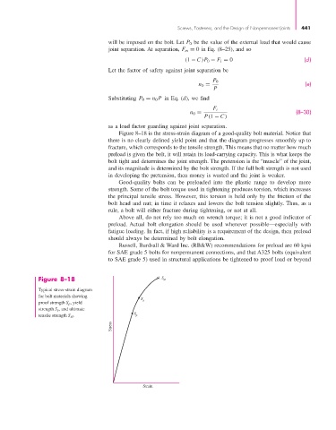
Figure 8–18 is the stress-strain diagram of a good-quality bolt material. Notice that
there is no clearly defined yield point and that the diagram progresses smoothly up to
fracture, which corresponds to the tensile strength. This means that no matter how much
preload is given the bolt, it will retain its load-carrying capacity. This is what keeps the
bolt tight and determines the joint strength. The pretension is the “muscle” of the joint,
and its magnitude is determined by the bolt strength. If the full bolt strength is not used
in developing the pretension, then money is wasted and the joint is weaker.
Good-quality bolts can be preloaded into the plastic range to develop more
strength. Some of the bolt torque used in tightening produces torsion, which increases
the principal tensile stress. However, this torsion is held only by the friction of the
bolt head and nut; in time it relaxes and lowers the bolt tension slightly. Thus, as a
rule, a bolt will either fracture during tightening, or not at all.
Above all, do not rely too much on wrench torque; it is not a good indicator of
preload. Actual bolt elongation should be used whenever possible—especially with
fatigue loading. In fact, if high reliability is a requirement of the design, then preload
should always be determined by bolt elongation.
Russell, Burdsall & Ward Inc. (RB&W) recommendations for preload are 60 kpsi
for SAE grade 5 bolts for nonpermanent connections, and that A325 bolts (equivalent
to SAE grade 5) used in structural applications be tightened to proof load or beyond
Figure 8–18 S ut
Typical stress-strain diagram
for bolt materials showing S
proof strength S p , yield y
strength S y , and ultimate
tensile strength S ut . S p
Stress
Strain