
Page 469 - Shigley's Mechanical Engineering Design
P. 469
bud29281_ch08_409-474.qxd 12/16/2009 7:11 pm Page 444 pinnacle 203:MHDQ196:bud29281:0073529281:bud29281_pagefiles:
444 Mechanical Engineering Design
8–10 Gasketed Joints
If a full gasket is present in the joint, the gasket pressure p is found by dividing the
force in the member by the gasket area per bolt. Thus, for N bolts,
F m
p =− (a)
A g /N
With a load factor n, Eq. (8–25) can be written as
F m = (1 − C)nP − F i (b)
Substituting this into Eq. (a) gives the gasket pressure as
N
p = [F i − nP(1 − C)] (8–33)
A g
In full-gasketed joints uniformity of pressure on the gasket is important. To main-
tain adequate uniformity of pressure adjacent bolts should not be placed more than six
nominal diameters apart on the bolt circle. To maintain wrench clearance, bolts should
be placed at least three diameters apart. A rough rule for bolt spacing around a bolt
circle is
π D b
3 ≤ ≤ 6 (8–34)
Nd
where D b is the diameter of the bolt circle and N is the number of bolts.
8–11 Fatigue Loading of Tension Joints
Tension-loaded bolted joints subjected to fatigue action can be analyzed directly by
the methods of Chap. 6. Table 8–16 lists average fatigue stress-concentration factors
for the fillet under the bolt head and also at the beginning of the threads on the bolt
shank. These are already corrected for notch sensitivity and for surface finish.
Designers should be aware that situations may arise in which it would be advisable
to investigate these factors more closely, since they are only average values. In fact,
9
Peterson observes that the distribution of typical bolt failures is about 15 percent
under the head, 20 percent at the end of the thread, and 65 percent in the thread at
the nut face.
Use of rolled threads is the predominant method of thread-forming in screw fas-
teners, where Table 8–16 applies. In thread-rolling, the amount of cold work and strain-
strengthening is unknown to the designer; therefore, fully corrected (including K f )
axial endurance strength is reported in Table 8–17. For cut threads, the methods of
Chap. 6 are useful. Anticipate that the endurance strengths will be considerably lower.
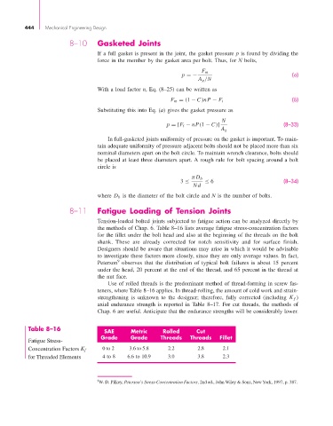
Table 8–16 SAE Metric Rolled Cut
Fatigue Stress- Grade Grade Threads Threads Fillet
0 to 2 3.6 to 5.8 2.2 2.8 2.1
Concentration Factors K f
for Threaded Elements 4 to 8 6.6 to 10.9 3.0 3.8 2.3
9 W. D. Pilkey, Peterson’s Stress-Concentration Factors, 2nd ed., John Wiley & Sons, New York, 1997, p. 387.