
Page 473 - Shigley's Mechanical Engineering Design
P. 473
bud29281_ch08_409-474.qxd 12/16/2009 7:11 pm Page 448 pinnacle 203:MHDQ196:bud29281:0073529281:bud29281_pagefiles:
448 Mechanical Engineering Design
Bolts loosen, as they are friction devices, and cyclic loading and vibration as well as
other effects allow the fasteners to lose tension with time. How does one fight loosening?
Within strength limitations, the higher the preload the better. A rule of thumb is that pre-
loads of 60 percent of proof load rarely loosen. If more is better, how much more? Well,
not enough to create reused fasteners as a future threat. Alternatively, fastener-locking
schemes can be employed.
After solving for the fatigue factor of safety, you should also check the possibility
of yielding, using the proof strength
S p
n p = (8–51)
σ m + σ a
which is equivalent to Eq. (8–28).
EXAMPLE 8–5 Figure 8–21 shows a connection using cap screws. The joint is subjected to a fluctu-
ating force whose maximum value is 5 kip per screw. The required data are: cap screw,
1
5/8in-11 NC, SAE 5; hardened-steel washer, t w = 16 in thick; steel cover plate, t 1 =
5 5 in, E ci = 16 Mpsi.
8 in, E s = 30 Mpsi; and cast-iron base, t 2 = 8
(a) Find k b , k m , and C using the assumptions given in the caption of Fig. 8–21.
(b) Find all factors of safety and explain what they mean.
Solution (a) For the symbols of Figs. 8–15 and 8–21, h = t 1 + t w = 0.6875 in, l = h + d/2 =
1 in, and D 2 = 1.5d = 0.9375 in. The joint is composed of three frusta; the upper
two frusta are steel and the lower one is cast iron.
For the upper frustum: t = l/2 = 0.5 in, D = 0.9375 in, and E = 30 Mpsi. Using
these values in Eq. (8–20) gives k 1 = 46.46 Mlbf/in.
For the middle frustum: t = h − l/2 = 0.1875 in and D = 0.9375 + 2(l − h)
tan 30 = 1.298 in. With these and E s = 30 Mpsi, Eq. (8–20) gives k 2 = 197.43 Mlbf/in.
◦
The lower frustum has D = 0.9375 in, t = l − h = 0.3125 in, and E ci = 16 Mpsi.
The same equation yields k 3 = 32.39 Mlbf/in.
Substituting these three stiffnesses into Eq. (8–18) gives k m = 17.40 Mlbf/in. The
cap screw is short and threaded all the way. Using l = 1 in for the grip and
2
A t = 0.226 in from Table 8–2, we find the stiffness to be k b = A t E/l = 6.78
Mlbf/in. Thus the joint constant is
6.78
k b
Answer C = = = 0.280
k b + k m 6.78 + 17.40
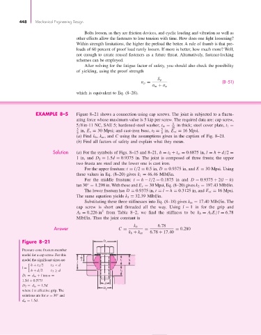
Figure 8–21 D 1
Pressure-cone frustum member
model for a cap screw. For this l
model the significant sizes are 2 t 1 h
l
h + t 2 /2 t 2 < d
l =
h + d/2 t 2 ≥ d t 2
D 1 = d w + l tan α =
1.5d + 0.577l
d
D 2 = d w = 1.5d
D
where l = effective grip. The 2
solutions are for α = 30 and
◦
d w = 1.5d.