Page 478 - Shigley's Mechanical Engineering Design
P. 478

bud29281_ch08_409-474.qxd  12/16/2009  7:11 pm  Page 453 pinnacle 203:MHDQ196:bud29281:0073529281:bud29281_pagefiles:


                                                                       Screws, Fasteners, and the Design of Nonpermanent Joints  453
                                                  Edge shearing, or tearing, of the margin is shown in Fig. 8–23f and g, respec-
                                               tively. In structural practice this failure is avoided by spacing the rivets at least 1 1 2
                                               diameters away from the edge. Bolted connections usually are spaced an even greater
                                               distance than this for satisfactory appearance, and hence this type of failure may usu-
                                               ally be neglected.
                                                  In a rivet joint, the rivets all share the load in shear, bearing in the rivet, bearing
                                               in the member, and shear in the rivet. Other failures are participated in by only some
                                               of the joint. In a bolted joint, shear is taken by clamping friction, and bearing does
                                               not exist. When bolt preload is lost, one bolt begins to carry the shear and bearing
                                               until yielding slowly brings other fasteners in to share the shear and bearing. Finally,
                                               all participate, and this is the basis of most bolted-joint analysis if loss of bolt pre-
                                               load is complete. The usual analysis involves
                                               • Bearing in the bolt (all bolts participate)
                                               • Bearing in members (all holes participate)
                                               • Shear of bolt (all bolts participate eventually)
                                               • Distinguishing between thread and shank shear
                                               • Edge shearing and tearing of member (edge bolts participate)
                                               • Tensile yielding of member across bolt holes
                                               • Checking member capacity


                                                                                                        1
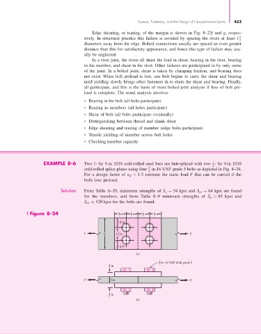
                             EXAMPLE 8–6       Two 1- by 4-in 1018 cold-rolled steel bars are butt-spliced with two  - by 4-in 1018
                                                                                                        2
                                                                           3
                                               cold-rolled splice plates using four  in-16 UNF grade 5 bolts as depicted in Fig. 8–24.
                                                                           4
                                               For a design factor of n d = 1.5 estimate the static load F that can be carried if the
                                               bolts lose preload.
                                    Solution   From Table A–20, minimum strengths of S y = 54 kpsi and S ut = 64 kpsi are found
                                               for the members, and from Table 8–9 minimum strengths of S p = 85 kpsi and
                                               S ut = 120 kpsi for the bolts are found.

                       Figure 8–24                           1 in  1 in  1 in  1 in
                                                                   1
                                                              1
                                                                         1
                                                                              1
                                                              2    2     2    2
                                                               1
                                                              1 in
                                                               4
                                                              1
                                               F       w     1 in                             F
                                                              2
                                                               1
                                                              1 in
                                                               4
                                                                      (a)
                                                                                3 in-16 UNF SAE grade 5
                                                          1  in                 4
                                                          2
                                               F          1in                                 F

                                                          1  in
                                                          2
                                                                      (b)
   473   474   475   476   477   478   479   480   481   482   483