Page 479 - Shigley's Mechanical Engineering Design
P. 479
bud29281_ch08_409-474.qxd  12/16/2009  7:11 pm  Page 454 pinnacle 203:MHDQ196:bud29281:0073529281:bud29281_pagefiles:


                 454    Mechanical Engineering Design
                                              F/2 is transmitted by each of the splice plates, but since the areas of the splice
                                          plates are half those of the center bars, the stresses associated with the plates are the
                                          same. So for stresses associated with the plates, the force and areas used will be those
                                          of the center plates.

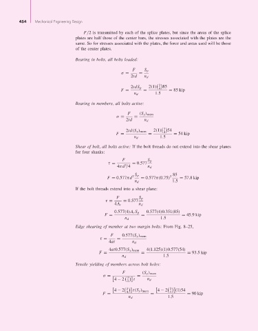
                                          Bearing in bolts, all bolts loaded:

                                                                    F    S p
                                                               σ =    =
                                                                   2td   n d
                                                                               3

                                                                           2(1)  85
                                                                   2tdS p      4
                                                              F =       =           = 85 kip
                                                                    n d       1.5
                                          Bearing in members, all bolts active:
                                                                 F     (S y ) mem
                                                            σ =     =
                                                                 2td     n d
                                                                                 3

                                                                 2td(S y ) mem  2(1)  4  54
                                                            F =            =          = 54 kip
                                                                    n d         1.5
                                          Shear of bolt, all bolts active: If the bolt threads do not extend into the shear planes
                                          for four shanks:
                                                               F          S p
                                                         τ =       = 0.577
                                                                2
                                                             4πd /4       n d
                                                                                      85
                                                                     S p
                                                        F = 0.577πd 2  = 0.577π(0.75) 2  = 57.8 kip
                                                                    n d              1.5
                                          If the bolt threads extend into a shear plane:
                                                            F         S p
                                                       τ =     = 0.577
                                                           4A r       n d
                                                           0.577(4)A r S p  0.577(4)0.351(85)
                                                       F =             =                  = 45.9 kip
                                                                n d             1.5
                                          Edge shearing of member at two margin bolts: From Fig. 8–25,

                                                          F    0.577(S y ) mem
                                                     τ =     =
                                                         4at       n d
                                                         4at0.577(S y ) mem  4(1.125)(1)0.577(54)
                                                     F =               =                    = 93.5 kip
                                                               n d               1.5
                                          Tensile yielding of members across bolt holes:
                                                               F        (S y ) mem
                                                                     =
                                                           4 − 2  4  t    n d
                                                      σ =        3
                                                                 3
                                                                                    3
                                                           4 − 2    t(S y ) mem  4 − 2  (1)54

                                                      F =        4          =       4       = 90 kip
                                                                  n d              1.5

