
Page 477 - Shigley's Mechanical Engineering Design
P. 477
bud29281_ch08_409-474.qxd 12/16/2009 7:11 pm Page 452 pinnacle 203:MHDQ196:bud29281:0073529281:bud29281_pagefiles:
452 Mechanical Engineering Design
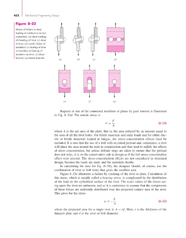
Figure 8–23
Modes of failure in shear
loading of a bolted or riveted
connection: (a) shear loading;
(b) bending of rivet; (c) shear
of rivet; (d) tensile failure of
members; (e) bearing of rivet
on members or bearing of
members on rivet; (f) shear
tear-out; (g) tensile tear-out.
(a) (b) (c) (d)
(e) ( f ) (g)
Rupture of one of the connected members or plates by pure tension is illustrated
in Fig. 8–23d. The tensile stress is
F
σ = (8–54)
A
where A is the net area of the plate, that is, the area reduced by an amount equal to
the area of all the rivet holes. For brittle materials and static loads and for either duc-
tile or brittle materials loaded in fatigue, the stress-concentration effects must be
included. It is true that the use of a bolt with an initial preload and, sometimes, a rivet
will place the area around the hole in compression and thus tend to nullify the effects
of stress concentration, but unless definite steps are taken to ensure that the preload
does not relax, it is on the conservative side to design as if the full stress-concentration
effect were present. The stress-concentration effects are not considered in structural
design, because the loads are static and the materials ductile.
In calculating the area for Eq. (8–54), the designer should, of course, use the
combination of rivet or bolt holes that gives the smallest area.
Figure 8–23e illustrates a failure by crushing of the rivet or plate. Calculation of
this stress, which is usually called a bearing stress, is complicated by the distribution
of the load on the cylindrical surface of the rivet. The exact values of the forces act-
ing upon the rivet are unknown, and so it is customary to assume that the components
of these forces are uniformly distributed over the projected contact area of the rivet.
This gives for the stress
F
σ =− (8–55)
A
where the projected area for a single rivet is A = td. Here, t is the thickness of the
thinnest plate and d is the rivet or bolt diameter.