Page 481 - Shigley's Mechanical Engineering Design
P. 481

bud29281_ch08_409-474.qxd  12/16/2009  7:11 pm  Page 456 pinnacle 203:MHDQ196:bud29281:0073529281:bud29281_pagefiles:


                 456    Mechanical Engineering Design
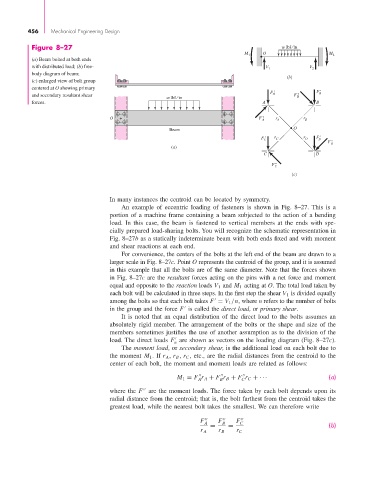
                  Figure 8–27                                                                  w lbf ⁄ in
                                                                                   M 1   O                   M 2
                  (a) Beam bolted at both ends
                  with distributed load; (b) free-                                        V            V
                                                                                           1            2
                  body diagram of beam;
                                                                                                 (b)
                  (c) enlarged view of bolt group
                  centered at O showing primary
                  and secondary resultant shear                                            F ' A   F " B  F ' B
                                                           w lbf ⁄ in
                  forces.                                                                A                B
                                          O  +                                          F " A  r A    r B
                                                                                                   O
                                                            Beam
                                                                                         F ' C  r C   r D  F ' D
                                                                                                             F " D
                                                             (a)
                                                                                         C               D

                                                                                            F " C
                                                                                                  (c)


                                          In many instances the centroid can be located by symmetry.
                                              An example of eccentric loading of fasteners is shown in Fig. 8–27.  This is a
                                          portion of a machine frame containing a beam subjected to the action of a bending
                                          load. In this case, the beam is fastened to vertical members at the ends with spe-
                                          cially prepared load-sharing bolts. You will recognize the schematic representation in
                                          Fig. 8–27b as a statically indeterminate beam with both ends fixed and with moment
                                          and shear reactions at each end.
                                              For convenience, the centers of the bolts at the left end of the beam are drawn to a
                                          larger scale in Fig. 8–27c. Point O represents the centroid of the group, and it is assumed
                                          in this example that all the bolts are of the same diameter. Note that the forces shown
                                          in Fig. 8–27c are the resultant forces acting on the pins with a net force and moment
                                          equal and opposite to the reaction loads V 1 and M 1 acting at O. The total load taken by
                                          each bolt will be calculated in three steps. In the first step the shear V 1 is divided equally
                                          among the bolts so that each bolt takes F = V 1 /n, where n refers to the number of bolts

                                          in the group and the force F is called the direct load, or primary shear.

                                              It is noted that an equal distribution of the direct load to the bolts assumes an
                                          absolutely rigid member. The arrangement of the bolts or the shape and size of the
                                          members sometimes justifies the use of another assumption as to the division of the
                                          load. The direct loads  F are shown as vectors on the loading diagram (Fig. 8–27c).

                                                              n
                                              The moment load, or secondary shear, is the additional load on each bolt due to
                                          the moment  M 1 . If r A , r B , r C , etc., are the radial distances from the centroid to the
                                          center of each bolt, the moment and moment loads are related as follows:

                                                                                                              (a)
                                                               M 1 = F r A + F r B + F r C + ···
                                                                                   C
                                                                            B
                                                                     A
                                          where the  F are the moment loads. The force taken by each bolt depends upon its

                                          radial distance from the centroid; that is, the bolt farthest from the centroid takes the
                                          greatest load, while the nearest bolt takes the smallest. We can therefore write
                                                                      F A     F B     F C
                                                                         =    =                               (b)
                                                                      r A   r B  r C
   476   477   478   479   480   481   482   483   484   485   486