
Page 482 - Shigley's Mechanical Engineering Design
P. 482
bud29281_ch08_409-474.qxd 12/16/2009 7:11 pm Page 457 pinnacle 203:MHDQ196:bud29281:0073529281:bud29281_pagefiles:
Screws, Fasteners, and the Design of Nonpermanent Joints 457
where again, the diameters of the bolts are assumed equal. If not, then one replaces
2
F in Eq. (b) with the shear stresses τ = 4F /πd for each bolt. Solving Eqs. (a)
and (b) simultaneously, we obtain
M 1 r n
(8–57)
F = 2 2 2
n
r + r + r +· · ·
A B C
where the subscript n refers to the particular bolt whose load is to be found. These
moment loads are also shown as vectors on the loading diagram.
In the third step the direct and moment loads are added vectorially to obtain the
resultant load on each bolt. Since all the bolts or rivets are usually the same size, only
that bolt having the maximum load need be considered. When the maximum load is
found, the strength may be determined by using the various methods already described.
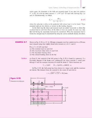
EXAMPLE 8–7 Shown in Fig. 8–28 is a 15- by 200-mm rectangular steel bar cantilevered to a 250-mm
steel channel using four tightly fitted bolts located at A, B, C, and D.
For a F = 16 kN load find
(a) The resultant load on each bolt
(b) The maximum shear stress in each bolt
(c) The maximum bearing stress
(d) The critical bending stress in the bar
Solution (a) Point O, the centroid of the bolt group in Fig. 8–28, is found by symmetry. If a
free-body diagram of the beam were constructed, the shear reaction V would pass
through O and the moment reactions M would be about O. These reactions are
V = 16 kN M = 16(425) = 6800 N · m
In Fig. 8–29, the bolt group has been drawn to a larger scale and the reactions
are shown. The distance from the centroid to the center of each bolt is
2
2
r = (60) + (75) = 96.0mm
Figure 8–28 250
Dimensions in millimeters. 10 15
M16 2 bolts
F = 16 kN
C B
60
200
O
D A 60
75 75 50 300