
Page 483 - Shigley's Mechanical Engineering Design
P. 483
bud29281_ch08_409-474.qxd 12/16/2009 7:11 pm Page 458 pinnacle 203:MHDQ196:bud29281:0073529281:bud29281_pagefiles:
458 Mechanical Engineering Design
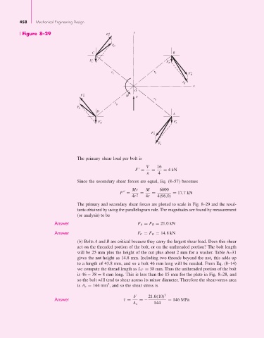
Figure 8–29 F C " y
F C
C B
F'
C F B '
r r F"
C B
B
F B
x
O
"
F D M
V
r
A
r
D
F D
D
A
' '
F D F A
"
F A
F A
The primary shear load per bolt is
V 16
= 4kN
F = =
n 4
Since the secondary shear forces are equal, Eq. (8–57) becomes
Mr M 6800
= 17.7kN
F = = =
4r 2 4r 4(96.0)
The primary and secondary shear forces are plotted to scale in Fig. 8–29 and the resul-
tants obtained by using the parallelogram rule. The magnitudes are found by measurement
(or analysis) to be
Answer F A = F B = 21.0kN
Answer F C = F D = 14.8kN
(b) Bolts A and B are critical because they carry the largest shear load. Does this shear
act on the threaded portion of the bolt, or on the unthreaded portion? The bolt length
will be 25 mm plus the height of the nut plus about 2 mm for a washer. Table A–31
gives the nut height as 14.8 mm. Including two threads beyond the nut, this adds up
to a length of 43.8 mm, and so a bolt 46 mm long will be needed. From Eq. (8–14)
we compute the thread length as L T = 38 mm. Thus the unthreaded portion of the bolt
is 46 − 38 = 8 mm long. This is less than the 15 mm for the plate in Fig. 8–28, and
so the bolt will tend to shear across its minor diameter. Therefore the shear-stress area
2
is A s = 144 mm , and so the shear stress is
F 21.0(10) 3
Answer τ = =− = 146 MPa
A s 144