
Page 480 - Shigley's Mechanical Engineering Design
P. 480
bud29281_ch08_409-474.qxd 12/16/2009 7:11 pm Page 455 pinnacle 203:MHDQ196:bud29281:0073529281:bud29281_pagefiles:
Screws, Fasteners, and the Design of Nonpermanent Joints 455
Member yield:
wt(S y ) mem 4(1)54
F = = = 144 kip
n d 1.5
On the basis of bolt shear, the limiting value of the force is 45.9 kip, assuming the
threads extend into a shear plane. However, it would be poor design to allow the threads
to extend into a shear plane. So, assuming a good design based on bolt shear, the lim-
iting value of the force is 57.8 kip. For the members, the bearing stress limits the load
to 54 kip.
Figure 8–25
Edge shearing of member. Bolt
d
a
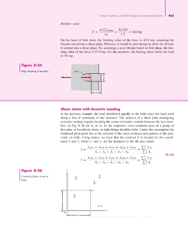
Shear Joints with Eccentric Loading
In the previous example, the load distributed equally to the bolts since the load acted
along a line of symmetry of the fasteners. The analysis of a shear joint undergoing
eccentric loading requires locating the center of relative motion between the two mem-
bers. In Fig. 8–26 let A 1 to A 5 be the respective cross-sectional areas of a group of
five pins, or hot-driven rivets, or tight-fitting shoulder bolts. Under this assumption the
rotational pivot point lies at the centroid of the cross-sectional area pattern of the pins,
rivets, or bolts. Using statics, we learn that the centroid G is located by the coordi-
nates ¯x and ¯y, where x 1 and y i are the distances to the ith area center:
n
A 1 x 1 + A 2 x 2 + A 3 x 3 + A 4 x 4 + A 5 x 5 1 A i x i
¯ x = = n
A 1 + A 2 + A 3 + A 4 + A 5 1 A i
n (8–56)
A 1 y 1 + A 2 y 2 + A 3 y 3 + A 4 y 4 + A 5 y 5 1 A i y i
¯ y = = n
A 1 + A 2 + A 3 + A 4 + A 5 1 A i
Figure 8–26 y
Centroid of pins, rivets, or A 2 A 3
bolts.
A 4
G
A 1
_
y
A 5
x
O
_
x