
Page 57 - Shigley's Mechanical Engineering Design
P. 57
bud29281_ch02_031-070.qxd 11/11/09 09:31 PM Page 32 Debd Hard Disk1:Desktop Folder:Temp Work:Satya 10/11/09:
32 Mechanical Engineering Design
The selection of a material for a machine part or a structural member is one of the most
important decisions the designer is called on to make. The decision is usually made
before the dimensions of the part are established. After choosing the process of creat-
ing the desired geometry and the material (the two cannot be divorced), the designer can
proportion the member so that loss of function can be avoided or the chance of loss of
function can be held to an acceptable risk.
In Chaps. 3 and 4, methods for estimating stresses and deflections of machine
members are presented. These estimates are based on the properties of the material
from which the member will be made. For deflections and stability evaluations, for
example, the elastic (stiffness) properties of the material are required, and evaluations
of stress at a critical location in a machine member require a comparison with the
strength of the material at that location in the geometry and condition of use. This
strength is a material property found by testing and is adjusted to the geometry and con-
dition of use as necessary.
As important as stress and deflection are in the design of mechanical parts, the
selection of a material is not always based on these factors. Many parts carry no loads
on them whatever. Parts may be designed merely to fill up space or for aesthetic quali-
ties. Members must frequently be designed to also resist corrosion. Sometimes temper-
ature effects are more important in design than stress and strain. So many other factors
besides stress and strain may govern the design of parts that the designer must have the
versatility that comes only with a broad background in materials and processes.
2–1 Material Strength and Stiffness
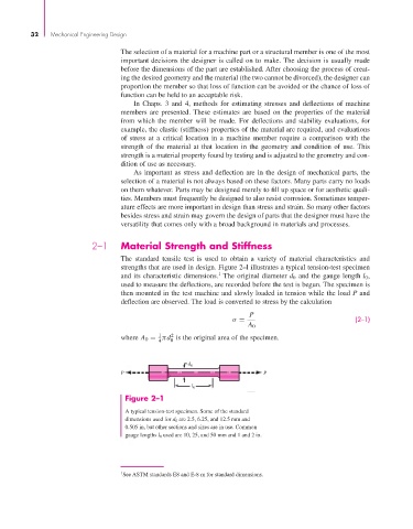
The standard tensile test is used to obtain a variety of material characteristics and
strengths that are used in design. Figure 2–l illustrates a typical tension-test specimen
1
and its characteristic dimensions. The original diameter d 0 and the gauge length l 0 ,
used to measure the deflections, are recorded before the test is begun. The specimen is
then mounted in the test machine and slowly loaded in tension while the load P and
deflection are observed. The load is converted to stress by the calculation
P
σ = (2–1)
A 0
1
2
where A 0 = πd is the original area of the specimen.
4 0
d 0
P P
l 0
Figure 2–1
A typical tension-test specimen. Some of the standard
dimensions used for d 0 are 2.5, 6.25, and 12.5 mm and
0.505 in, but other sections and sizes are in use. Common
gauge lengths l 0 used are 10, 25, and 50 mm and 1 and 2 in.
1 See ASTM standards E8 and E-8 m for standard dimensions.