
Page 139 - Six Sigma for electronics design and manufacturing
P. 139
Six Sigma for Electronics Design and Manufacturing
108
PCB assembly process quality can be enhanced with better employ-
ee training, the use of more automation such as autoinsertion of
through hole (TH) and auto placement of SMT components, and im-
proving the design guidelines of PCBs. Design guidelines might in-
clude standards for component polarity indicators, component
placement and orientation in one axis, pad, hole and line geometry,
and graphic placement aids.
Soldering quality can be improved by continuously upgrading sol-
dering materials and processes with the latest technology avail-
able, and performing design of experiment (DoE) techniques to op-
timally meet the soldering process parameters.
4.3 Determining Design or Manufacturing Yield on
Multiple Parts with Multiple Manufacturing
Operations or Design Specifications
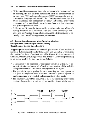
A typical production line consists of multiple sources of materials and
multiple distinct operations for fabrication and assembly of parts into
the next-higher level of product assembly. Figure 4.2 is an example of
a multistep manufacturing process line. Some of the issues pertaining
to six sigma quality for this line are as follows:
If the line is to be upgraded to six sigma quality, it is logical to as-
sume that, at a minimum, all of the incoming parts and the individ-
ual operations of the line are to be upgraded to six sigma.
The goal of six sigma quality for each incoming part and operation
is a good management tool, since the individual part or operation
can be analyzed or upgraded, independently of other parts.
The output quality of the line, even if all of the incoming component
parts and operations are of six sigma quality, is not at six sigma.
Figure 4.2 An example of a multistep manufacturing process line.