
Page 336 -
P. 336
CHAPTER 12 ANALYSIS MODELING 307
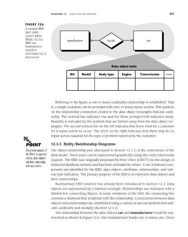
FIGURE 12.6
A simple ERD
and data
object table
(Note: In this
manufacturer builds car
ERD the
relationship
builds is
indicated by a
diamond)
Data object table
ID# Model Body type Engine Transmission • • •
Referring to the figure, a one to many cardinality relationship is established. That
is, a single customer can be provided with zero or many repair actions. The symbols
on the relationship connection closest to the data object rectangles indicate cardi-
nality. The vertical bar indicates one and the three-pronged fork indicates many.
Modality is indicated by the symbols that are further away from the data object rec-
tangles. The second vertical bar on the left indicates that there must be a customer
for a repair action to occur. The circle on the right indicates that there may be no
repair action required for the type of problem reported by the customer.
12.3.3 Entity/Relationship Diagrams
The primary purpose of The object/relationship pair (discussed in Section 12.3.1) is the cornerstone of the
the ERD is to represent data model. These pairs can be represented graphically using the entity/relationship
entities (data objects) diagram. The ERD was originally proposed by Peter Chen [CHE77] for the design of
and their relationships
with one another. relational database systems and has been extended by others. A set of primary com-
ponents are identified for the ERD: data objects, attributes, relationships, and vari-
ous type indicators. The primary purpose of the ERD is to represent data objects and
their relationships.
Rudimentary ERD notation has already been introduced in Section 12.3. Data
objects are represented by a labeled rectangle. Relationships are indicated with a
labeled line connecting objects. In some variations of the ERD, the connecting line
contains a diamond that is labeled with the relationship. Connections between data
objects and relationships are established using a variety of special symbols that indi-
cate cardinality and modality (Section 12.3.2).
The relationship between the data objects car and manufacturer would be rep-
resented as shown in Figure 12.6. One manufacturer builds one or many cars. Given