
Page 339 -
P. 339
310 PART THREE CONVENTIONAL METHODS FOR SOFTWARE ENGINEERING
External Input data External
entity entity
Intermediate
Transform data
#1
Transform Intermediate Output data
#3 data
Intermediate
data
Transform
#4
Data store Data store
Transform input output
External #2
entity Data store Output data
Input data
External
entity
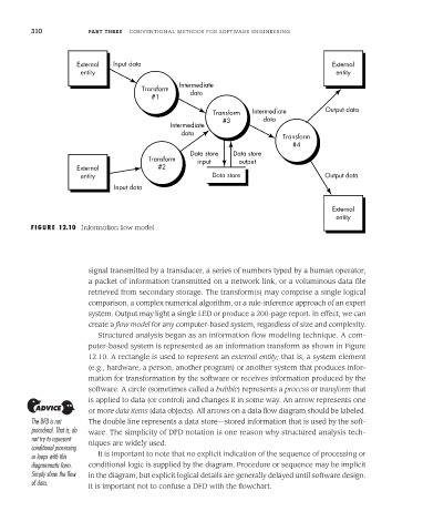
FIGURE 12.10 Information flow model
signal transmitted by a transducer, a series of numbers typed by a human operator,
a packet of information transmitted on a network link, or a voluminous data file
retrieved from secondary storage. The transform(s) may comprise a single logical
comparison, a complex numerical algorithm, or a rule-inference approach of an expert
system. Output may light a single LED or produce a 200-page report. In effect, we can
create a flow model for any computer-based system, regardless of size and complexity.
Structured analysis began as an information flow modeling technique. A com-
puter-based system is represented as an information transform as shown in Figure
12.10. A rectangle is used to represent an external entity; that is, a system element
(e.g., hardware, a person, another program) or another system that produces infor-
mation for transformation by the software or receives information produced by the
software. A circle (sometimes called a bubble) represents a process or transform that
is applied to data (or control) and changes it in some way. An arrow represents one
or more data items (data objects). All arrows on a data flow diagram should be labeled.
The DFD is not The double line represents a data store—stored information that is used by the soft-
procedural. That is, do ware. The simplicity of DFD notation is one reason why structured analysis tech-
not try to represent
conditional processing niques are widely used.
or loops with this It is important to note that no explicit indication of the sequence of processing or
diagrammatic form. conditional logic is supplied by the diagram. Procedure or sequence may be implicit
Simply show the flow in the diagram, but explicit logical details are generally delayed until software design.
of data.
It is important not to confuse a DFD with the flowchart.