
Page 343 -
P. 343
314 PART THREE CONVENTIONAL METHODS FOR SOFTWARE ENGINEERING
FIGURE 12.13 Movement
Data and Status of each alarm
control flows fixture
using Ward
and Mellor Parts status buffer Robot
notation initiation
[WAR85] Start/stop control
Bit string
flag
Monitor Process
fixture & activate
operator
interface
Position
Operator Operator
commands settings Process commands
robot
commands
Robot movement
record
Robot command file
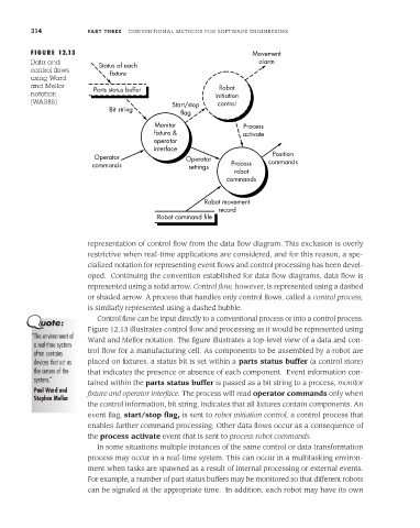
representation of control flow from the data flow diagram. This exclusion is overly
restrictive when real-time applications are considered, and for this reason, a spe-
cialized notation for representing event flows and control processing has been devel-
oped. Continuing the convention established for data flow diagrams, data flow is
represented using a solid arrow. Control flow, however, is represented using a dashed
or shaded arrow. A process that handles only control flows, called a control process,
is similarly represented using a dashed bubble.
Control flow can be input directly to a conventional process or into a control process.
Figure 12.13 illustrates control flow and processing as it would be represented using
“The environment of Ward and Mellor notation. The figure illustrates a top-level view of a data and con-
a real-time system
often contains trol flow for a manufacturing cell. As components to be assembled by a robot are
devices that act as placed on fixtures, a status bit is set within a parts status buffer (a control store)
the senses of the that indicates the presence or absence of each component. Event information con-
system.”
tained within the parts status buffer is passed as a bit string to a process, monitor
Paul Ward and fixture and operator interface. The process will read operator commands only when
Stephen Mellor
the control information, bit string, indicates that all fixtures contain components. An
event flag, start/stop flag, is sent to robot initiation control, a control process that
enables further command processing. Other data flows occur as a consequence of
the process activate event that is sent to process robot commands.
In some situations multiple instances of the same control or data transformation
process may occur in a real-time system. This can occur in a multitasking environ-
ment when tasks are spawned as a result of internal processing or external events.
For example, a number of part status buffers may be monitored so that different robots
can be signaled at the appropriate time. In addition, each robot may have its own