Page 37 - Solid Waste Analysis and Minimization a Systems Approach
P. 37

THE SYSTEMS APPROACH FOR WASTE MINIMIZATION             15


                        1
                            2
                     0

                           3


                                 4          5

                                                 6
                                                         7
                                                                 8
                                                                           9


                                                                                        10

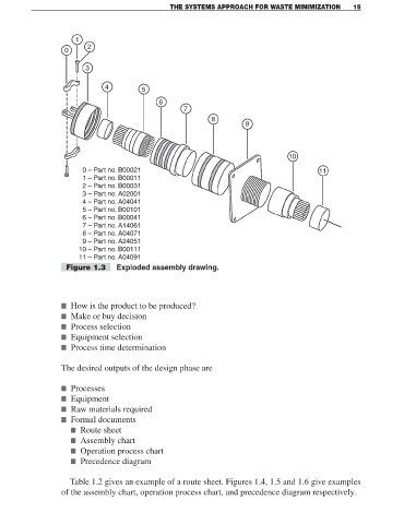
                          0 – Part no. B00021                                                     11
                          1 – Part no. B00011
                          2 – Part no. B00031
                          3 – Part no. A02001
                          4 – Part no. A04041
                          5 – Part no. B00101
                          6 – Part no. B00041
                          7 – Part no. A14061
                          8 – Part no. A04071
                          9 – Part no. A24051
                         10 – Part no. B00111
                         11 – Part no. A04091
                     Figure 1.3     Exploded assembly drawing.


                    ■ How is the product to be produced?
                    ■ Make or buy decision
                    ■ Process selection
                    ■ Equipment selection
                    ■ Process time determination


                    The desired outputs of the design phase are


                    ■ Processes
                    ■ Equipment
                    ■ Raw materials required
                    ■ Formal documents
                      ■ Route sheet
                      ■ Assembly chart
                      ■ Operation process chart
                      ■ Precedence diagram


                      Table 1.2 gives an example of a route sheet. Figures 1.4, 1.5 and 1.6 give examples
                    of the assembly chart, operation process chart, and precedence diagram respectively.
   32   33   34   35   36   37   38   39   40   41   42