
Page 39 - Solid Waste Analysis and Minimization a Systems Approach
P. 39
THE SYSTEMS APPROACH FOR WASTE MINIMIZATION 17
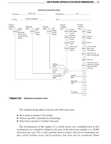
OPERATION PROCESS CHART
A.R.C., Inc. J. A.
Company Prepared by
Air Flow Regulator
Product Date
Plunger Plunger Plunger
retainer Seat ring Plunger housing housing
4150 Shape, 3250 Shape, 3252 Mill, 3254 Shape, 2200
drill drill, shape, Cut to
0105 0102 0103 0104 drill, length 0101
tap inside cut off, cut off, cut off length
thread, hook inspect inspect
outside thread, Machine Grind to
inspect 0204 slot and 0201 length
thread
Drill (8)
0304 0301 Deburr
holes
Deburr and Drill (4) holes,
0404 blowout 0401 tap, ream,
inspect countersink
Drill, tap, roll
0501
ream, countersink
0601 Drill, tap
Remove burrs on
Spring inside and inspect
0701
3253 inner and outer
surfaces
O-ring
SA1 A1
3251
O-ring, 3255 Locknut
A2
3656 4250
Pipe plug
A3
1050
I1
Packaging
A4
Figure 1.5 Operation process chart.
The schedule design phase examines the following issues:
■ How much to produce? (lot sizing)
■ When to produce? (production scheduling)
■ How long to produce? (market forecasts)
The determination of the outputs of a system seems very straightforward at first
examination, as it should be defined in the goal. In the television example, it is 30,000
televisions per year. This is only a partial answer as there will also be unintended out-
puts, which includes waste and by-products, that must also be considered. Waste