
Page 205 - Standard Handbook Of Petroleum & Natural Gas Engineering
P. 205
190 General Engineering and Science
Transverse Loading of Beams
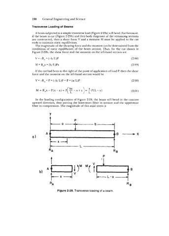
A beam subjected to a simple transverse load (Figure 2-29a) will bend. Furthermore,
if the beam is cut (Figure 2-2913) and free-body diagrams of the remaining sections
are constructed, then a shear force V and a moment M must be applied to the cut
ends to maintain static equilibrium.
The magnitude of the shearing force and the moment can be determined from the
conditions of static equilibrium of the beam section. Thus, for the cut shown in
Figure 2-29b, the shear force and the moment on the left-hand section are
V = -RA = (-b/L)P (2-88)
M = RAx = (b/L)Px (2-89)
If the cut had been to the right of the point of application of load P, then the shear
force and the moment on the left-hand section would be
V = -R, + P = (-b/L)P + P = (a/L)P (2-90)
(2-91)
In the loading configuration of Figure 2-29, the beam will bend in the concave
upward direction, thus putting the lowermost fiber in tension and the uppermost
fiber in compression. The magnitude of this axial stress is
Y
P
RA RR
t
RA
Figure 2-29. Transverse loading of a beam.