
Page 69 - Sustainability in the Process Industry Integration and Optimization
P. 69
46 Cha p te r F o u r
capital cost. In most industries, the bulk of the heat exchange must
occur without mixing the heat-exchanging streams. In order to
exchange only heat while keeping the streams separate, surface heat
exchangers are employed. In these devices, heat is exchanged through
a dividing wall. Because of its high thermal efficiency, the counter-
current stream arrangement is the most common with surface
heat exchangers. To simplify the discussion, counter-current heat
exchangers are assumed unless stated otherwise. In terms of
construction types, the traditional shell-and-tube heat exchanger is
still the most common. However, plate-type and other compact heat
exchangers are gaining increased attention. Their compactness,
together with significant improvements in their resistance to leaking,
have made them preferable in many cases.
4.1.1 Heat Exchange Matches
A hot process stream can supply heat to a cold one when paired in
one or several physical heat exchangers arranged in parallel or
sequence. Each such pairing is referred to as a heat exchange match.
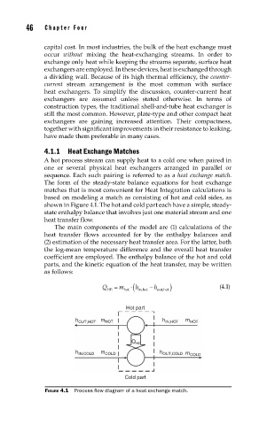
The form of the steady-state balance equations for heat exchange
matches that is most convenient for Heat Integration calculations is
based on modeling a match as consisting of hot and cold sides, as
shown in Figure 4.1. The hot and cold part each have a simple, steady-
state enthalpy balance that involves just one material stream and one
heat transfer flow.
The main components of the model are (1) calculations of the
heat transfer flows accounted for by the enthalpy balances and
(2) estimation of the necessary heat transfer area. For the latter, both
the log-mean temperature difference and the overall heat transfer
coefficient are employed. The enthalpy balance of the hot and cold
parts, and the kinetic equation of the heat transfer, may be written
as follows:
m Q h h (4.1)
HE hot out,hot in,hot
Hot part
h OUT,HOT m HOT h IN,HOT m HOT
Q HE
h IN,COLD m COLD h OUT,COLD m COLD
Cold part
FIGURE 4.1 Process fl ow diagram of a heat exchange match.