
Page 71 - Sustainability in the Process Industry Integration and Optimization
P. 71
48 Cha p te r F o u r
Ambient
Utilities
Separator Separator
Feed Heat Exchanger Network
Reactor
Feed + Product Reactor
Product
Steam Turbine
Boiler
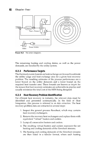
FIGURE 4.2 The onion diagram.
The remaining heating and cooling duties, as well as the power
demands, are handled by the utility system.
4.2.3 Performance Targets
The thermodynamic bounds on heat exchange can be used to estimate
the utility usage and heat exchange area for a given heat recovery
problem. The resulting estimates of the process performance are a
lower bound on the utility demands and a lower bound on the
required heat transfer area. These bounds are known as targets for
the reason that heat recovery estimates are achievable in practice and
usually minimize the total cost of the HEN being designed.
4.2.4 Heat Recovery Problem Identification
For efficient heat recovery in industry, the relevant data must be
identified and presented systematically. In the field of Heat
Integration, this process is referred to as data extraction. The heat
recovery problem data are extracted in several steps:
1. Inspect the general process flowsheet, which may contain
heat recovery exchangers.
2. Remove the recovery heat exchangers and replace them with
equivalent “virtual” heaters and coolers.
3. Lump all consecutive heaters and coolers.
4. The resulting virtual heaters and coolers represent the net
heating and cooling demands of the flowsheet streams.
5. The heating and cooling demands of the flowsheet streams
are then listed in a tabular format, where each heating