
Page 221 - Materials Chemistry, Second Edition
P. 221
Ch006-P373623.qxd 3/22/07 5:36 PM Page 200
Sustainable Industrial Design and Waste Management
200
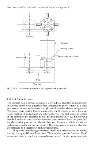
Top view
Container
Rotating blades
Stationary blades
Motor
Belts
Front view
FIGURE 6.2 Schematic diagram of the agglomeration machine
Indirect flame furnace
The indirect flame furnace consists of a cylindrical chamber equipped with
an electric motor with a gearbox that transmits its power output to a three
gear system located at the top of the cylindrical chamber shown in Figure 6.3.
The gears rotate mixing blades in two different directions to stir a homoge-
neous mixture of heated sand and other additives. The fuel burner is located
at the bottom of the chamber to heat the mix indirectly. A 1/3 hp blower is
attached to the mixing chamber to collect gases emitted from the paste dur-
ing the heating process into the combustion chamber to minimize the air
pollution generated during the process. The temperature inside the chamber
is controlled by a thermostat and a control panel.
The plastic from the agglomeration machine is mixed with sand and fed
through the upper lid into the furnace. The machine operates for about 30–40
minutes in order to reach the required temperature. The stirring action starts