
Page 351 - Sustainable On-Site CHP Systems Design, Construction, and Operations
P. 351
324 Ca s e S t u d y 1
Dillon Gym mechanical room. These produce approximately 500 kW while controlling
the steam pressure between the 200-psig high-pressure distribution system and the 15-
psig low-pressure distribution system on campus. This was the first installation where
two Microsteam systems have been operated in parallel.
Central Energy Plant and Systems
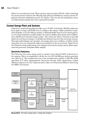
Princeton’s central energy plant provides up to 15 MW of electricity, 300,000 pounds per
hour (pph) of steam, and 25,000 tons of cooling to the campus. Major production equip-
ment includes: a GE LM-1600 gas turbine, a Nebraska Boiler heat recovery steam genera-
tor, two dual fuel Indeck auxiliary boilers, five electric chillers, three steam-driven chillers,
and a 40,000 ton-h thermal storage system. This varied mix allows Princeton to provide
electricity and thermal energy in a reliable and efficient manner to the university campus.
Through careful design and operation, the energy plant saves millions of dollars for the
university each year and greatly reduces net emissions to the environment. Figure 19-2 is
the Princeton energy plant energy flow diagram showing the energy inputs, plant equip-
ment and processes, and plant utility outputs.
Electricity Production
The Princeton University energy plant is capable of providing 15 MW of electricity to
the campus. This is accomplished with the use of a GE LM-1600 gas turbine generator
(see Table 19-1). The nominal heat rate of the aeroderivative turbine is 9983 Btu/kWh
(gas fired, 55°F inlet), approximately 34 percent efficient. With cogeneration, system
efficiency improves to over 73 percent and is often over 80 percent efficient when firing
the HRSG duct burner.
PSEG
electricity
Electricity
Natural Gas turbine
gas & Backpressure
HRSG turbines
Steam Campus
No.2 diesel energy users
fuel oil Duct burner
& Chilled water
HRSG
&
Biodiesel
thermal Chilled
fuel oil
storage water
Auxiliary
boilers systems
FIGURE 19-2 Princeton energy plant—energy fl ow diagram.