
Page 352 - Sustainable On-Site CHP Systems Design, Construction, and Operations
P. 352
Princeton University District Ener gy System 325
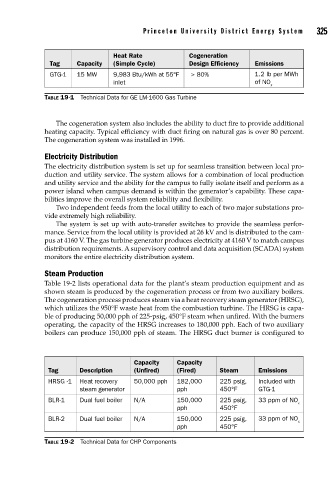
Heat Rate Cogeneration
Tag Capacity (Simple Cycle) Design Efficiency Emissions
GTG-1 15 MW 9,983 Btu/kWh at 55°F > 80% 1.2 lb per MWh
inlet of NO
x
TABLE 19-1 Technical Data for GE LM-1600 Gas Turbine
The cogeneration system also includes the ability to duct fire to provide additional
heating capacity. Typical efficiency with duct firing on natural gas is over 80 percent.
The cogeneration system was installed in 1996.
Electricity Distribution
The electricity distribution system is set up for seamless transition between local pro-
duction and utility service. The system allows for a combination of local production
and utility service and the ability for the campus to fully isolate itself and perform as a
power island when campus demand is within the generator’s capability. These capa-
bilities improve the overall system reliability and flexibility.
Two independent feeds from the local utility to each of two major substations pro-
vide extremely high reliability.
The system is set up with auto-transfer switches to provide the seamless perfor-
mance. Service from the local utility is provided at 26 kV and is distributed to the cam-
pus at 4160 V. The gas turbine generator produces electricity at 4160 V to match campus
distribution requirements. A supervisory control and data acquisition (SCADA) system
monitors the entire electricity distribution system.
Steam Production
Table 19-2 lists operational data for the plant’s steam production equipment and as
shown steam is produced by the cogeneration process or from two auxiliary boilers.
The cogeneration process produces steam via a heat recovery steam generator (HRSG),
which utilizes the 950°F waste heat from the combustion turbine. The HRSG is capa-
ble of producing 50,000 pph of 225-psig, 450°F steam when unfired. With the burners
operating, the capacity of the HRSG increases to 180,000 pph. Each of two auxiliary
boilers can produce 150,000 pph of steam. The HRSG duct burner is configured to
Capacity Capacity
Tag Description (Unfired) (Fired) Steam Emissions
HRSG -1 Heat recovery 50,000 pph 182,000 225 psig, Included with
steam generator pph 450°F GTG-1
BLR-1 Dual fuel boiler N/A 150,000 225 psig, 33 ppm of NO
x
pph 450°F
BLR-2 Dual fuel boiler N/A 150,000 225 psig, 33 ppm of NO
x
pph 450°F
TABLE 19-2 Technical Data for CHP Components