
Page 384 - Sustainable On-Site CHP Systems Design, Construction, and Operations
P. 384
University Campus CHP Analysis 357
Cogeneration Equipment
The cogeneration plant consists of
• Two combustion turbine generator sets
• Two heat recovery steam generators (HRSGs), with integrated natural gas–fired
duct burners
Each of the turbine generators has a capacity of approximately 5 MW of electricity
at 13.8 kV and can produce 25,000 lb/h of steam at 275 psig in the unfired HRSG. When
the duct burners within the HRSG operate, the total steam production of each HRSG
increases from 25,000 lb/h to 65,000 lb/h of saturated 275-psig steam, for a combined
output of 130,000 lb/h. Firing the duct burners to increase the steam generation capacity
is possible with the combustion turbine exhaust gases that are rich in oxygen and at
high temperature. The additional 40,000 lb/h of steam are produced at 94.5 percent
efficiency, which is considerably higher than the efficiency of a steam boiler. Table 22-2
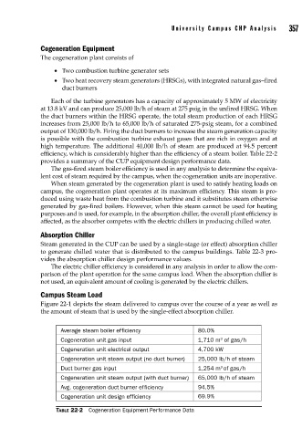
provides a summary of the CUP equipment design performance data.
The gas-fired steam boiler efficiency is used in any analysis to determine the equiva-
lent cost of steam required by the campus, when the cogeneration units are inoperative.
When steam generated by the cogeneration plant is used to satisfy heating loads on
campus, the cogeneration plant operates at its maximum efficiency. This steam is pro-
duced using waste heat from the combustion turbine and it substitutes steam otherwise
generated by gas-fired boilers. However, when this steam cannot be used for heating
purposes and is used, for example, in the absorption chiller, the overall plant efficiency is
affected, as the absorber competes with the electric chillers in producing chilled water.
Absorption Chiller
Steam generated in the CUP can be used by a single-stage (or effect) absorption chiller
to generate chilled water that is distributed to the campus buildings. Table 22-3 pro-
vides the absorption chiller design performance values.
The electric chiller efficiency is considered in any analysis in order to allow the com-
parison of the plant operation for the same campus load. When the absorption chiller is
not used, an equivalent amount of cooling is generated by the electric chillers.
Campus Steam Load
Figure 22-1 depicts the steam delivered to campus over the course of a year as well as
the amount of steam that is used by the single-effect absorption chiller.
Average steam boiler efficiency 80.0%
3
Cogeneration unit gas input 1,710 m of gas/h
Cogeneration unit electrical output 4,700 kW
Cogeneration unit steam output (no duct burner) 25,000 lb/h of steam
3
Duct burner gas input 1,254 m of gas/h
Cogeneration unit steam output (with duct burner) 65,000 lb/h of steam
Avg. cogeneration duct burner efficiency 94.5%
Cogeneration unit design efficiency 69.9%
TABLE 22-2 Cogeneration Equipment Performance Data