
Page 50 - Sustainable On-Site CHP Systems Design, Construction, and Operations
P. 50
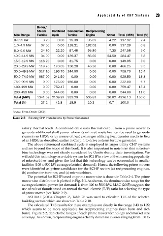
Applicability of CHP Systems     29


                      Boiler/
                      Steam   Combined  Combustion  Reciprocating
         Size Range   Turbine  Cycle   Turbine    Engine      Other  Total (MW) Total (%)
         0–999 kW        3.23     0.00  15.38      95.09       4.22  117.92      2.4
         1.0–4.9 MW     37.06     0.00  118.21    182.02       0.00  337.29      6.8
         5.0–9.9 MW     24.80   22.20   97.48      95.80       7.30  247.58      5.0
         10.0–14.9 MW   34.00     0.00  139.37     86.60      24.50  284.47      5.8
         15.0–19.9 MW  118.20     0.00  31.75       0.00       0.00  149.95      3.0
         20.0–29.9 MW  119.70  170.05  130.20      46.30       0.00  466.25      9.5
         30.0–49.9 MW  317.10  196.70  244.90       0.00       0.00  758.70    15.4
         50.0–74.9 MW  687.00  241.50    0.00       0.00       0.00  928.50    18.8
         75.0–99.9 MW    0.00  176.00  156.00       0.00       0.00  332.00      6.7
         100–199 MW      0.00  759.47    0.00       0.00       0.00  759.47    15.4
         200–499 MW      0.00  544.00    0.00       0.00       0.00  544.00    11.0
         Total (MW)   1341.09 2109.92  933.29     505.81      36.02 4926.13   100.0
         Total (%)      27.2    42.8    18.9       10.3        0.7   100.0

        Source: From Onsite (2000).

        TABLE 2-8  Existing CHP Installations by Power Generated

             satisfy thermal loads. A combined cycle uses thermal output from a prime mover to
             generate additional shaft power where its exhaust waste heat can be used to generate
             steam in an HRSG or by means of heat exchanger utilizing heat transfer media in lieu
             of an HRSG as described earlier in Chap. 1 to drive a steam turbine generator.
                The above referenced combined cycle is employed in larger utility CHP systems
             and are beyond the scope of this book. It is also important to note here that microtur-
             bine technology was not clearly considered by Onsite during their investigation. We
             will add this technology as a viable system for BCHP in view of the increasing popularity
             of microturbines, and given the fact that this technology can be economical in smaller
             facilities (100 to 500 kW average electrical demand). Hence, the following prime movers
             were identified as prime candidates for the BCHP sector: (a) reciprocating engines,
             (b) combustion turbines, and (c) microturbines.
                The potential for BCHP based on prime mover size is shown in Table 2-4. The prime
             mover size distribution is plotted in Fig. 2-1. As shown, the dominant size range for the
             average electrical power (or demand) is from 100 to 5000 kW. MAC (2005) suggests the
             use of rule of thumb based on annual thermal-electric (T/E) ratio for selecting the type
             of prime mover (see Table 2-9).
                ASHRAE (2003), Chapter 35, Table 2B was used to calculate T/E of the selected
             building sectors which are shown in Table 2.10.
                The calculated T/E results for these examples are clearly in the range 0.43 to 1.22
             which seems to be more applicable for reciprocating engines (lean burn and rich
             burn). Figure 2-2, depicts the ranges of each prime mover technology and market size
             coverage. As shown, reciprocating engines clearly dominate in sizes ranging from 100 to