
Page 98 - The Art and Science of Analog Circuit Design
P. 98
Steve Roach
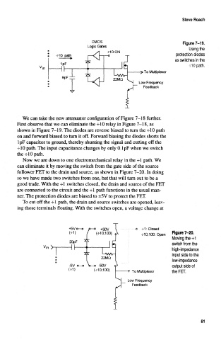
CMOS Figure 7-19,
Logic Gates
Using the
-MOON
protection diodes
as switches in the
•flO path.
To Multiplexor
Low Frequency
Feedback
We can take the new attenuator configuration of Figure 7-18 further.
First observe that we can eliminate the -f 10 relay in Figure 7-18, as
shown in Figure 7-19. The diodes are reverse biased to turn the -flO path
on and forward biased to turn it off. Forward biasing the diodes shorts the
IpF capacitor to ground, thereby shunting the signal and cutting off the
-10 path. The input capacitance changes by only 0.1 pF when we switch
the -r 10 path.
Now we are down to one electromechanical relay in the -rl path. We
can eliminate it by moving the switch from the gate side of the source
follower FET to the drain and source, as shown in Figure 7-20. In doing
so we have made two switches from one, but that will turn out to be a
good trade. With the -fl switches closed, the drain and source of the FET
are connected to the circuit and the 4-1 path functions in the usual man-
ner. The protection diodes are biased to ±5V to protect the FET.
To cut off the -rl path, the drain and source switches are opened, leav-
ing those terminals floating. With the switches open, a voltage change at
+5Vo—o o—o +5QV \ -f-1: Closed
(-5-1) / (-5-10,100) A •1-10,100: Open Figyre 7-20.
Moving the -fl
20pF
switch from the
Vir / I - •"-•—• •< high-impedance
-2s: LVSA^ input side to the
» 22MQ
f
* low-impedance
-5V o—o V- o -50V o output side of
Of ) 010,100) ">• To Multiplexor the FET.
Low Frequency
Feedback
81