
Page 93 - The Art and Science of Analog Circuit Design
P. 93
Signal Conditioning in Oscilloscopes and the Spirit of invention
-HO V,
SQQ
R2 _ . . R1
P eCISIOn
aOOKQ j; 4.7MQ
Op-amp
Bipolar Transistor
Current Source
R3 R6
200K£i 4KQ
R7
1KQ
R5
'offset 1
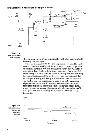
Figure 7-13.
A two-path imped-
ance converter.
Thus we avoid putting an AC coupling relay, with all its parasitic effects,
in the high-frequency path.
There are drawbacks to the two-path impedance converter. The small
flatness errors shown in Figure 7-14 never seem to go away, regardless
of the many alternative two-path architectures we try. Also, Cl forms a
capacitive voltage divider with the input capacitance of the source fol-
lower. Along with the fact that the source follower gain is less than unity,
this means that the gain of the low-frequency path may not match that
of the high-frequency path. Component variations cause the flatness to
vary further. Since the impedance converter is driven by a precision
high-impedance attenuator, it must have a very well-behaved input
impedance that closely resembles a simple RC parallel circuit. In this
regard the most common problem occurs when the op amp has insuffi-
cient speed and fails to bootstrap Rl in Figure 7-13 to high enough
frequencies.
990m-
Figure 7-14,
Flatness details of +0.1% error
the two-path
impedance
-0.1% error
converter.
980m ._„_ „ j -
I.OmHz 1.0KHz 100MHz
Frequency
76