
Page 97 - The Art and Science of Analog Circuit Design
P. 97
Signal Conditioning in Oscilloscopes and the Spirit of Invention
>V out
Low Frequency
Gain Control
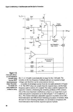
Figure 7-18.
A two-path attenua-
tor and impedance
converter using the -rl or -f-10 path is automatically in range for the -Hi00 path. The
only two SPST switches in the low-frequency feedback path are not exposed to high
electromechanical voltages and therefore can be semiconductor devices.
relays. The protec- A number of advantages accrue from the two-path attenuator of Figure
tion diodes and 7-18. The SPST relays are simpler than the original relays, and the high-
some resistors are frequency path is entirely AC coupled! The relays could be replaced with
omitted for clarity. capacitive switches, eliminating the reliability problems of DC contacts.
One of the most important contributions is that we no longer have to pre-
cisely trim passive components as we did in Figure 7-15 to make RjC t =
R 2C 2. This feature eliminates adjustable capacitors in printed circuit (PC)
board attenuators and difficult laser trimming procedures on hybrids. With
the need for laser trimming eliminated, we can build on inexpensive PC
board attenuators that formerly required expensive hybrids.
80