
Page 150 - The Combined Finite-Discrete Element Method
P. 150
DEFORMATION GRADIENT 133
~
k
x = f(p) ~ j
~
i
y
j
k
p i
y
z x
j
i
x
k
z
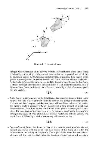
Figure 4.2 Frames of reference.
changes with deformation of the discrete element. The orientation of the initial frame
is defined by a triad of generally non-unit vectors that are, in general, not parallel to
the respective axes of the Cartesian coordinate system. In addition, these vectors are in
general not orthogonal to each other. Initially, this frame coincides with the local frame.
As the body deforms, this frame begins to differ from the local frame. As this frame
is obtained through deformation of the local frame, it is in further text referred to as a
deformed local frame. A deformed local frame is defined by a triad of non-orthogonal
non-unit vectors:
˜ ˜ ˜
(i, j, k) (4.8)
• Initial frame: in the same way as the local frame, this reference frame is linked to the
material point and is associated with the initial position of a particular discrete element.
It is therefore fixed in space, and does not move with the discrete element. Very often
this frame is made to coincide with, say, the edges of a finite element on a particular
discrete element. Thus, base vectors of this frame are in general not orthogonal to each
other. The magnitude of the base vectors is, for instance, equal to the length of the
corresponding edges of finite elements, i.e. the base vectors are not unit vectors. The
initial frame is defined by a triad of non-orthogonal non-unit vectors:
(i, j, k) (4.9)
• Deformed initial frame: this frame is fixed to the material point p of the discrete
element, and moves with that point. The base vectors of this frame also follow the
deformation in the vicinity of the point p. The origin of this frame thus coincides at
all times with the point x = f(p), while the direction of triad vectors and magnitude