
Page 270 - The Combined Finite-Discrete Element Method
P. 270
DISCRETE CRACK MODEL 253
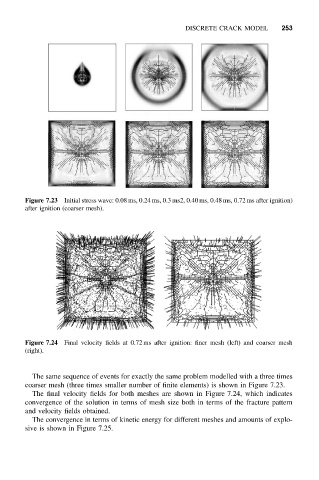
Figure 7.23 Initial stress wave: 0.08 ms, 0.24 ms, 0.3 ms2, 0.40 ms, 0.48 ms, 0.72 ms after ignition)
after ignition (coarser mesh).
Figure 7.24 Final velocity fields at 0.72 ms after ignition: finer mesh (left) and coarser mesh
(right).
The same sequence of events for exactly the same problem modelled with a three times
coarser mesh (three times smaller number of finite elements) is shown in Figure 7.23.
The final velocity fields for both meshes are shown in Figure 7.24, which indicates
convergence of the solution in terms of mesh size both in terms of the fracture pattern
and velocity fields obtained.
The convergence in terms of kinetic energy for different meshes and amounts of explo-
sive is shown in Figure 7.25.