
Page 268 - The Combined Finite-Discrete Element Method
P. 268
DISCRETE CRACK MODEL 251
(a) (b) (c)
(d) (e) (f)
(g) (h) (i)
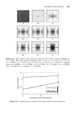
Figure 7.20 Finite element mesh (mesh D) employed and fracture sequence obtained for
2γ = 30 N/m. The frames shown correspond to (b) t = 0ms, (c) t = 0.17 ms, (d) t = 0.27 ms,
(e) t = 0.28 ms, (f) t = 0.30 ms, (g) t = 0.31 ms, (h) t = 0.32 ms, (i) t = 0.50 ms; i.e. transient
loads (b) σ = 0MPa, (c) σ = 3.4MPa, (d) σ = 5.4MPa, (e) σ = 5.6 MPa, (f) σ = 6.0MPa,
(g) σ = 6.2MPa, (h) σ = 6.4MPa, (i) σ = 10.0MPa.
7.5
Fracture load MPa 2.5 5
30 N/m
3 N/m
0
0 0.5 1
Normalised size of finite elements
Figure 7.21 Fracture load as a function of the energy release rate and element size.