
Page 264 - The Combined Finite-Discrete Element Method
P. 264
DISCRETE CRACK MODEL 247
(a) (b) (c)
(d) (e) (f)
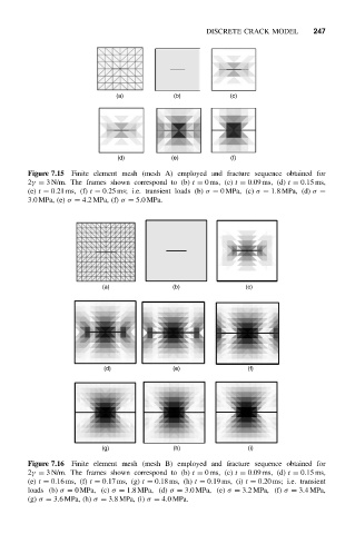
Figure 7.15 Finite element mesh (mesh A) employed and fracture sequence obtained for
2γ = 3 N/m. The frames shown correspond to (b) t = 0ms, (c) t = 0.09 ms, (d) t = 0.15 ms,
(e) t = 0.21 ms, (f) t = 0.25 ms; i.e. transient loads (b) σ = 0MPa, (c) σ = 1.8MPa, (d) σ =
3.0MPa, (e) σ = 4.2 MPa, (f) σ = 5.0MPa.
(a) (b) (c)
(d) (e) (f)
(g) (h) (i)
Figure 7.16 Finite element mesh (mesh B) employed and fracture sequence obtained for
2γ = 3 N/m. The frames shown correspond to (b) t = 0ms, (c) t = 0.09 ms, (d) t = 0.15 ms,
(e) t = 0.16 ms, (f) t = 0.17 ms, (g) t = 0.18 ms, (h) t = 0.19 ms, (i) t = 0.20 ms; i.e. transient
loads (b) σ = 0MPa, (c) σ = 1.8MPa, (d) σ = 3.0MPa, (e) σ = 3.2 MPa, (f) σ = 3.4MPa,
(g) σ = 3.6MPa, (h) σ = 3.8MPa, (i) σ = 4.0MPa.