
Page 262 - The Combined Finite-Discrete Element Method
P. 262
DISCRETE CRACK MODEL 245
s
2b
2a
s
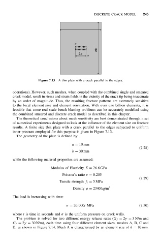
Figure 7.13 A thin plate with a crack parallel to the edges.
operations). However, such meshes, when coupled with the combined single and smeared
crack model, result in stress and strain fields in the vicinity of the crack tip being inaccurate
by an order of magnitude. Thus, the resulting fracture patterns are extremely sensitive
to the local element size and element orientation. With over one billion elements, it is
feasible that some real scale bench blasting problems can be accurately modelled using
the combined smeared and discrete crack model as described in this chapter.
The theoretical conclusions about mesh sensitivity are best demonstrated through a set
of numerical experiments designed to look at the influence of the element size on fracture
results. A finite size thin plate with a crack parallel to the edges subjected to uniform
inner pressure employed for this purpose is given in Figure 7.13.
The geometry of the plate is defined by:
a = 10 mm
(7.28)
b = 30 mm
while the following material properties are assumed:
Modulus of Elasticity E = 26.6GPa
Poisson’s ratio ν = 0.205
(7.29)
Tensile strength f t = 5MPa
Density ρ = 2340 kg/m 3
The load is increasing with time:
σ = 20,000t MPa (7.30)
where t is time in seconds and σ is the uniform pressure on crack walls.
The problem is solved for two different energy release rates (G f = 2γ = 3N/m and
G f = 2γ = 30 N/m), each time using four different element sizes, meshes A, B, C and
D, as shown in Figure 7.14. Mesh A is characterised by an element size of h = 10 mm.