
Page 269 - The Combined Finite-Discrete Element Method
P. 269
252 TRANSITION FROM CONTINUA TO DISCONTINUA
An exact solution would in theory be obtained by a finite element mesh comprising
zero size elements, as indicated by the point where the straight line intersects the y-axis.
The difference between the fracture loads obtained using meshes C and D is one half
of that from using meshes B and C, which in turn is one half of the difference between
fracture loads obtained using meshes A and B. In other words, if the element size is
halved, the error is also halved and the order of error as a function of element size h is
thus given by
ε = O(h) (7.32)
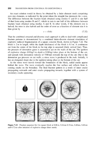
That the combined smeared and discrete crack approach is able to deal with complicated
fracture patterns is demonstrated by a combined finite-discrete element simulation of
explosive induced fragmentation of a square concrete block, shown in Figure 7.22. The
block is 2 m in length, while the depth (thickness) of the block is 0.1 m. A continuous
cut from the centre of the block to the top edge is assumed (thick vertical line). Thus,
the pressure of detonation gases is assumed to act on the walls of the cut. The ignition
of explosive charge (0.8 kg/1 m depth = 0.08 kg) takes place at the bottom of the cut,
and spreads with detonation velocity of 7580 m/s towards the top of the cut. Due to the
detonation gas pressure on cut walls, a stress wave is produced in the rock. Initially, it
has an elongated shape due to the ignition taking place at the bottom of the cut.
As the stress wave travels toward the boundaries of the block, radial cracks appear
behind the wave. The wave eventually reaches the free surface and reflects from it,
causing cracks on the boundary. The final fracture pattern is a result of inner cracks
propagating outwards and outer cracks propagating inwards, together with a system of
secondary cracks appearing.
Figure 7.22 Fracture sequence for 2 m square block at 0.08 m, 0.24 ms 0.32 ms, 0.40 ms, 0.48 ms
and 0.72 ms after initiation of explosive charge (finer mesh).