
Page 284 - The Combined Finite-Discrete Element Method
P. 284
GAS FLOW THROUGH FRACTURING SOLID 267
size of gas zone, while the area of individual ducts and the number of ducts is derived
from the current size and distribution of individual solid fragments within the gas zone.
• The spatial distribution of pressure within the gas zone is described by the pressure
drop within individual ducts.
• Gas flow at the entry to the duct is described by the steady state flow of ideal gas in a
converging no-friction duct.
8.3.1 Constant area duct
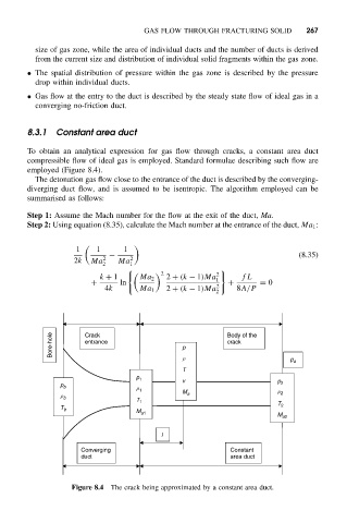
To obtain an analytical expression for gas flow through cracks, a constant area duct
compressible flow of ideal gas is employed. Standard formulae describing such flow are
employed (Figure 8.4).
The detonation gas flow close to the entrance of the duct is described by the converging-
diverging duct flow, and is assumed to be isentropic. The algorithm employed can be
summarised as follows:
Step 1: Assume the Mach number for the flow at the exit of the duct, Ma.
Step 2: Using equation (8.35), calculate the Mach number at the entrance of the duct, Ma 1 :
1
1 1
− (8.35)
2k Ma 2 Ma 2
2 1
/
2 2 0
k + 1 Ma 2 2 + (k − 1)Ma 1 fL
+ ln + = 0
4k Ma 1 2 + (k − 1)Ma 2 8A/P
2
Bore-hole Crack p Body of the
crack
entrance
r
p a
T
p 1
v p 2
p b
r 1
M a r 2
r b
T 1
T 2
T b
M a1
M a2
l
Converging Constant
duct area duct
Figure 8.4 The crack being approximated by a constant area duct.